
Shim support guide JIG for magnetic field generation apparatus, magnetic field generation apparatus and magnetic resonance imaging equipment each including shim support in which magnetic material shims are arranged and adjusted by employing shim support guide JIG, and magnetic field adjustment method for magnetic field generation apparatus, as well as magnetic field adjustment method for magnetic resonance imaging equipment

a technology of magnetic field generation apparatus and support guide jig, which is applied in the direction of instruments, magnetic measurements, measurement devices, etc., can solve the problems of large current, inability to safely arrange and adjust the support of the magnetic material shim, and the magnetic field space is less uniform

Inactive Publication Date: 2009-01-08
MITSUBISHI ELECTRIC CORP
View PDF14 Cites 35 Cited by
  • Summary
  • Abstract
  • Description
  • Claims
  • Application Information

AI Technical Summary

Benefits of technology

[0019]Owing to the use of the shim support guide jig according to this invention, in the state where the superconducting magnet has generated the magnetic field in the internal space, it is possible to draw out the designated shim support from the internal space to a place where the influence of the magnetic field becomes little, to perform the arrangement and adjustment of the magnetic material shims for the designated shim support in the place, and to insert the designated shim support into the internal space. Therefore, in the state where the superconducting magnet has generated the static magnetic field, the arrangement and adjustment of the magnetic material shims can be performed, and a time period required for the magnetic field adjustment can be shortened. Moreover, in the arrangement and adjustment of the magnetic material shims, the deexcitation and re-excitation of the superconducting magnet are dispensed with, and liquid helium can be prevented from decreasing due to its vaporization.
[0020]Besides, in the magnetic field generation apparatus according to this invention, at least one shim support designated among a plurality of shim supports has had the magnetic material shims arranged and adjusted in a state where it has been drawn out from an internal space via a guide passage formed in a shim support guide pipe of a shim support guide jig, and it has been thereafter inserted into the internal space via the guide passage. In a state where a superconducting magnet has generated a static magnetic field, the arrangement and adjustment of the magnetic material shims are performed, and hence, a time period required for a magnetic field adjustment is shortened. Moreover, in the arrangement and adjustment of the magnetic material shims, the deexcitation and re-excitation of the superconducting magnet are dispensed with, and liquid helium can be prevented from decreasing due to its vaporization.
[0021]Besides, the magnetic resonance imaging equipment according to this invention includes the magnetic field generation apparatus according to this invention, and it makes the magnetic resonance imaging diagnosis of a patient arranged in the internal space of a superconducting magnet. The magnetic field adjustment of the magnetic resonance imaging equipment can be performed in a state where the superconducting magnet has generated a magnetic field, and a time period required for a magnetic field adjustment can be shortened. Moreover, in the arrangement and adjustment of the magnetic material shims, the deexcitation and re-excitation of the superconducting magnet are dispensed with, and liquid helium can be prevented from decreasing due to its vaporization.
[0022]Besides, the magnetic field adjustment method for a magnetic field generation apparatus according to this invention includes drawing out at least one shim support designated among the plurality of shim supports, from the internal space via a guide passage formed in a shim support guide pipe of a shim support guide jig; accommodating the magnetic material shims of designative volume at a designative position of the designated shim support; and inserting the designated shim support in which the magnetic material shims have been accommodated, into the internal space via the guide passage. According to the magnetic field adjustment method for the magnetic field generation apparatus, the magnetic field adjustment based on the magnetic material shims can be performed in a state where a superconducting magnet has generated a magnetic field, and a time period required for a magnetic field adjustment can be shortened. Moreover, in the arrangement and adjustment of the magnetic material shims, the deexcitation and re-excitation of the superconducting magnet are dispensed with, and liquid helium can be prevented from decreasing due to its vaporization.
[0023]Further, the magnetic field adjustment method for a magnetic resonance imaging equipment according to this invention consists in a magnetic field adjustment method for a magnetic resonance imaging equipment which makes a magnetic resonance imaging diagnosis of a patient arranged in an internal space of a superconducting magnet, wherein a magnetic field adjustment is performed by employing the magnetic field adjustment method for the magnetic field generation apparatus according to this invention. According to the magnetic field adjustment method for the magnetic resonance imaging equipment, the arrangement and adjustment of the magnetic material shims can be performed in a state where the superconducting magnet has generated a magnetic field, and a time period required for a magnetic field adjustment can be shortened. Moreover, in the arrangement and adjustment of the magnetic material shims, the deexcitation and re-excitation of the superconducting magnet are dispensed with, and liquid helium can be prevented from decreasing due to its vaporization.

Problems solved by technology

In actuality, however, the uniformity of the magnetic field in the magnetic field space lowers due to a manufacturing dimensional error in a process for producing the superconducting magnet, the influence of a magnetic material existing around a place where the superconducting magnet is installed, and so forth.
In general, in a state where the superconducting magnet is excited to generate the static magnetic field, an intense electromagnetic force acts on the magnetic material shims, and hence, the magnetic material shims cannot be safely arranged and adjusted.
However, a long time, for example, about one hour is expended on each of the excitation and deexcitation of the superconducting magnet, and a time period of two hours or more is required for deexciting the superconducting magnet once and exciting it again.
As another problem, in deexciting and exciting the superconducting magnet, large currents must be caused to flow through current leads made of a normal conductor.

Method used


Image

  • Shim support guide JIG for magnetic field generation apparatus, magnetic field generation apparatus and magnetic resonance imaging equipment each including shim support in which magnetic material shims are arranged and adjusted by employing shim support guide JIG, and magnetic field adjustment method for magnetic field generation apparatus, as well as magnetic field adjustment method for magnetic resonance imaging equipment
  • Shim support guide JIG for magnetic field generation apparatus, magnetic field generation apparatus and magnetic resonance imaging equipment each including shim support in which magnetic material shims are arranged and adjusted by employing shim support guide JIG, and magnetic field adjustment method for magnetic field generation apparatus, as well as magnetic field adjustment method for magnetic resonance imaging equipment
  • Shim support guide JIG for magnetic field generation apparatus, magnetic field generation apparatus and magnetic resonance imaging equipment each including shim support in which magnetic material shims are arranged and adjusted by employing shim support guide JIG, and magnetic field adjustment method for magnetic field generation apparatus, as well as magnetic field adjustment method for magnetic resonance imaging equipment

Examples


embodiment 1

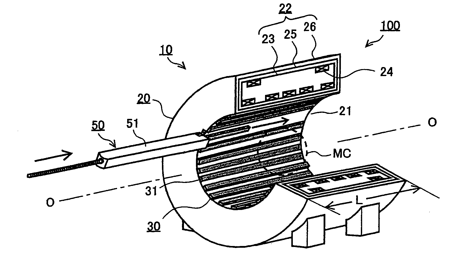
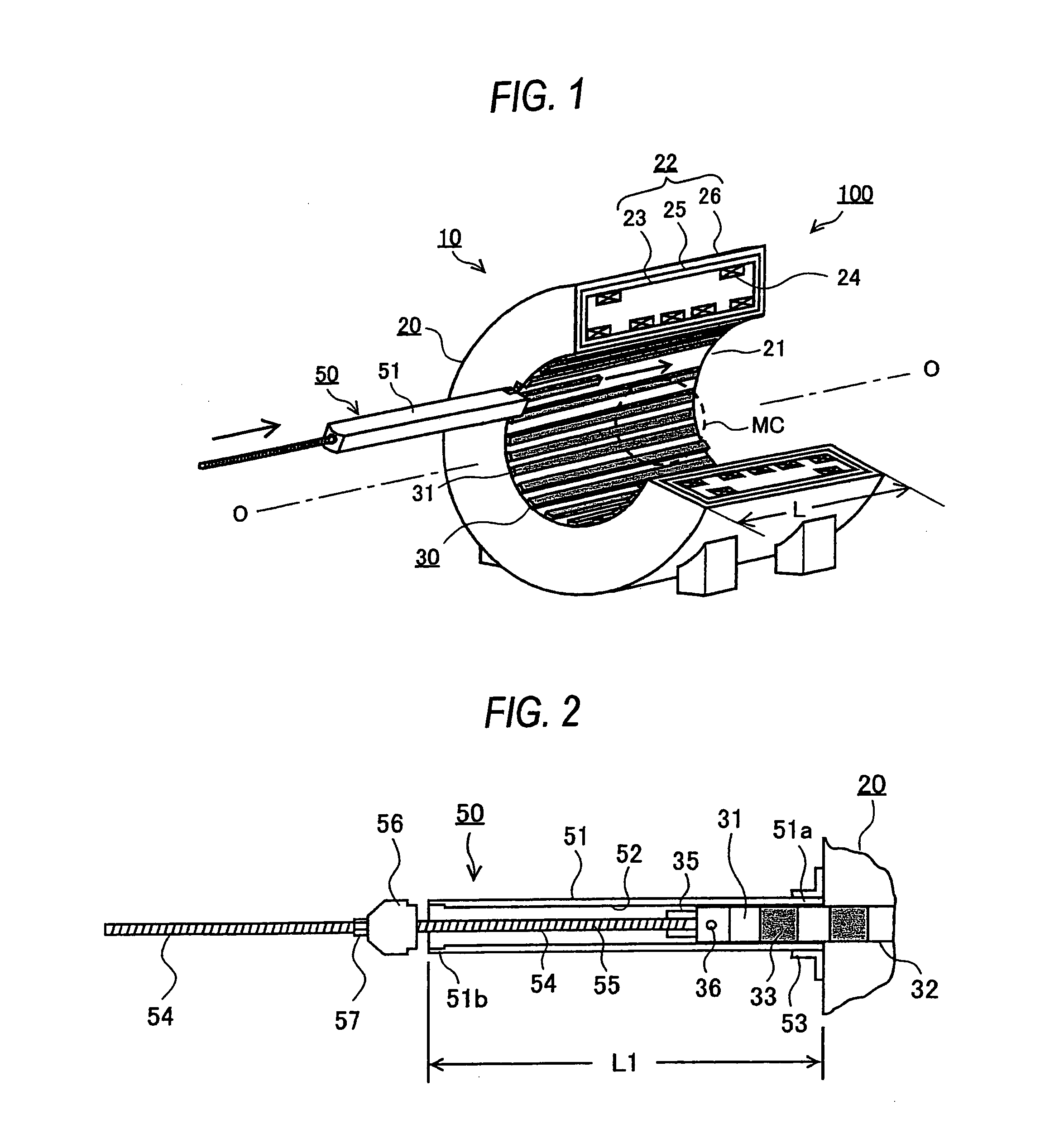
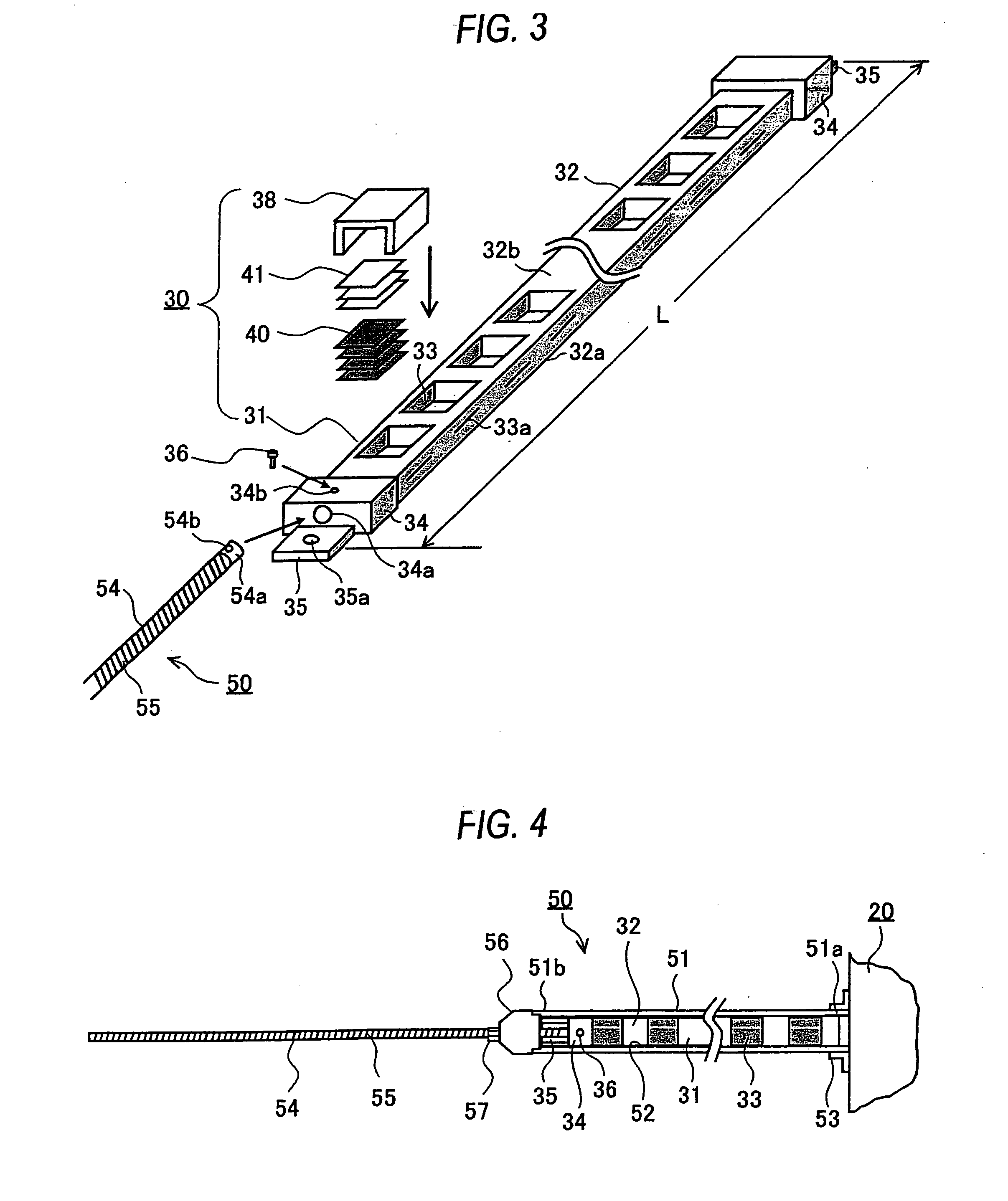
[0036]FIG. 1 is a perspective view, partly in section, showing a magnetic field adjustment state in Embodiment 1 of a magnetic resonance imaging equipment according to this invention. FIG. 2 is a sectional view showing Embodiment 1 of a shim support guide jig according to this invention. FIG. 3 is a perspective view showing the shim support guide jig according to Embodiment 1 and a shim support. FIG. 4 is a sectional view showing a state where the shim support has been drawn out by the shim support guide jig according to Embodiment 1.

[0037]A magnetic resonance imaging equipment 100 in Embodiment 1 as shown in FIG. 1 includes Embodiment 1 of a magnetic field generation apparatus according to this invention, and Embodiment 1 of a shim support guide jig according to this invention. The magnetic field generation apparatus in Embodiment 1 is indicated at numeral 10, and the shim support guide jig in Embodiment 1 is indicated at numeral 50.

[0038]As shown in FIG. 1, the magnetic field gene...

embodiment 2

[0072]FIG. 5 shows Embodiment 2 of the shim support guide jig according to this invention. The shim support guide jig 50A of Embodiment 2 shown in FIG. 5 is used instead of the shim support guide jig 50 of Embodiment 1 when the magnetic field adjustment of the magnetic field generation apparatus 10 is performed.

[0073]As compared with the shim support guide jig 50 of Embodiment 1 shown in FIG. 2, the shim support guide jig 50A of Embodiment 2 has removed the fixing lid 56 and the manipulating nut 57 in Embodiment 1, and it uses a manipulating gear 61 replacing the manipulating nut 57. A manipulating handle 62 is added to the manipulating gear 61, and it is connected to the manipulating gear 61 through pulleys 63 and 64 and a belt 65. The manipulating gear 61 is a worm gear which meshes with the screw 55 of a shim support connecting rod 54, and it is installed in the outer end portion 51b of a shim support guide pipe 51. This worm gear is not driven even when the large force of a shim...

embodiment 3

[0080]FIG. 6 shows Embodiment 3 of the shim support guide jig according to this invention, while FIG. 7 shows a shim support which is used in combination with the shim support guide jig of Embodiment 3. The shim support guide jig 50B of Embodiment 3 shown in FIG. 6 is used instead of the shim support guide jig 50 of Embodiment 1, and the shim support 31B shown in FIG. 7 is used instead of the shim support 31 of Embodiment 1. A plurality of shim supports 31B as shown in FIG. 7 are prepared, and they are arranged on the inner peripheral surface of a superconducting magnet 20, in parallel with a center axis O-O and at equal peripheral intervals.

[0081]As shown in FIG. 6, the shim support guide jig 50B of Embodiment 3 is such that a fixing lid 71 is detachably fixed to an outer end portion 51b, that a shim support connecting rod 54 is arranged so as to penetrate through the fixing lid 71, and that the outer periphery of the shim support connecting rod 54 is formed with a screw 55 in a ma...


PUM


Abstract

A shim support guide jig includes a shim support guide pipe in which a guide passage for guiding the movement of a shim support is formed. In a state where a superconducting magnet has generated a static magnetic field, the designated shim support can be drawn out from the internal space of the superconducting magnet through the guide passage, and the designated shim support for which magnetic material shims have been arranged and adjusted can be inserted into the internal space through the guide passage. A magnetic field generation apparatus has the magnetic material shims arranged and adjusted using the shim support guide jig, and a magnetic resonance imaging equipment employs the magnetic field generation apparatus. Magnetic field adjustment methods for the magnetic field generation apparatus and for the magnetic resonance imaging equipment are performed using the shim support guide jig.

Description

BACKGROUND OF THE INVENTION[0001]1. Field of the Invention[0002]This invention relates to a shim support guide jig for a magnetic field generation apparatus, a magnetic field generation apparatus and a magnetic resonance imaging equipment each including a shim support in which magnetic material shims are arranged and adjusted by employing a shim support guide jig, and a magnetic field adjustment method for a magnetic field generation apparatus, as well as a magnetic field adjustment method for a magnetic resonance imaging equipment.[0003]2. Description of the Related Art[0004]A magnetic field generation apparatus including a superconducting magnet is used in a magnetic resonance imaging equipment. The superconducting magnet is configured in a cylindrical shape, and it generates a static magnetic field in its internal space. A patient is arranged in the static magnetic field, and the image diagnosis of the patient is made.[0005]A magnetic field whose magnetic field strength is high, ...

Claims


Application Information

Patent Timeline
IPC IPC(8): G01V3/00
CPCG01R33/3873G01R33/3815
Inventor TAMURA, HAJIMETANABE, HAJIME
Owner MITSUBISHI ELECTRIC CORP
Learn More