
Vertical cavity surface emitting laser

Active Publication Date: 2021-10-28
RAYIR CO
View PDF0 Cites 0 Cited by
  • Summary
  • Abstract
  • Description
  • Claims
  • Application Information

AI Technical Summary

Benefits of technology

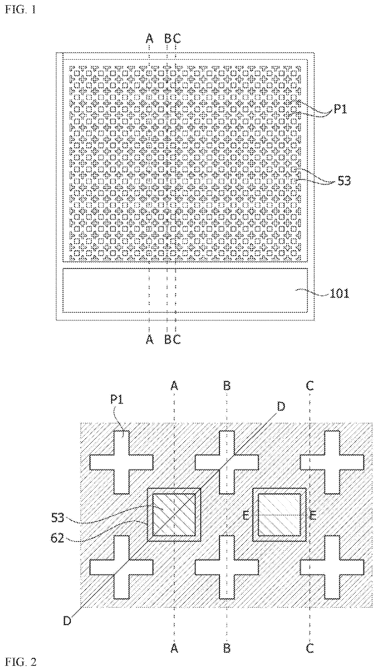
The present invention is directed toward improving a vertical cavity surface emitting laser by increasing the contact area of the ohmic electrode to decrease contact resistance. Additionally, it aims to enhance the efficiency and optical power output of the laser by increasing the density of unit light emitting regions (emitters) which emit lasers.

Problems solved by technology

In a case in which a plurality of emitters of lasers are formed in an array form, when the array is formed through the conventional manufacturing method, since a contact area of a semiconductor layer in contact with an ohmic electrode should be small, there is a problem in that a contact resistance increases.
Accordingly, there is a limitation to decreasing an operating voltage.

Method used


Image

  • Vertical cavity surface emitting laser
  • Vertical cavity surface emitting laser
  • Vertical cavity surface emitting laser

Examples


Embodiment Construction

[0037]As the present invention allows for various changes and numerous embodiments, specific embodiments will be illustrated in the drawings and described in detail in the written description. However, this is not intended to limit the present invention to specific embodiments, and it is to be appreciated that all changes, equivalents, and substitutes that do not depart from the spirit and technical scope of the present invention are encompassed in the present invention.

[0038]It will be understood that, although the terms “first,”“second,” etc. may be used herein to describe various elements, these elements should not be limited by these terms. These terms are only used to distinguish one element from another. For example, a first element could be termed a second element, and a second element could similarly be termed a first element without departing from the scope of the present invention. As used herein, the term “and / or” includes combinations or any one of a plurality of associa...


PUM


Abstract

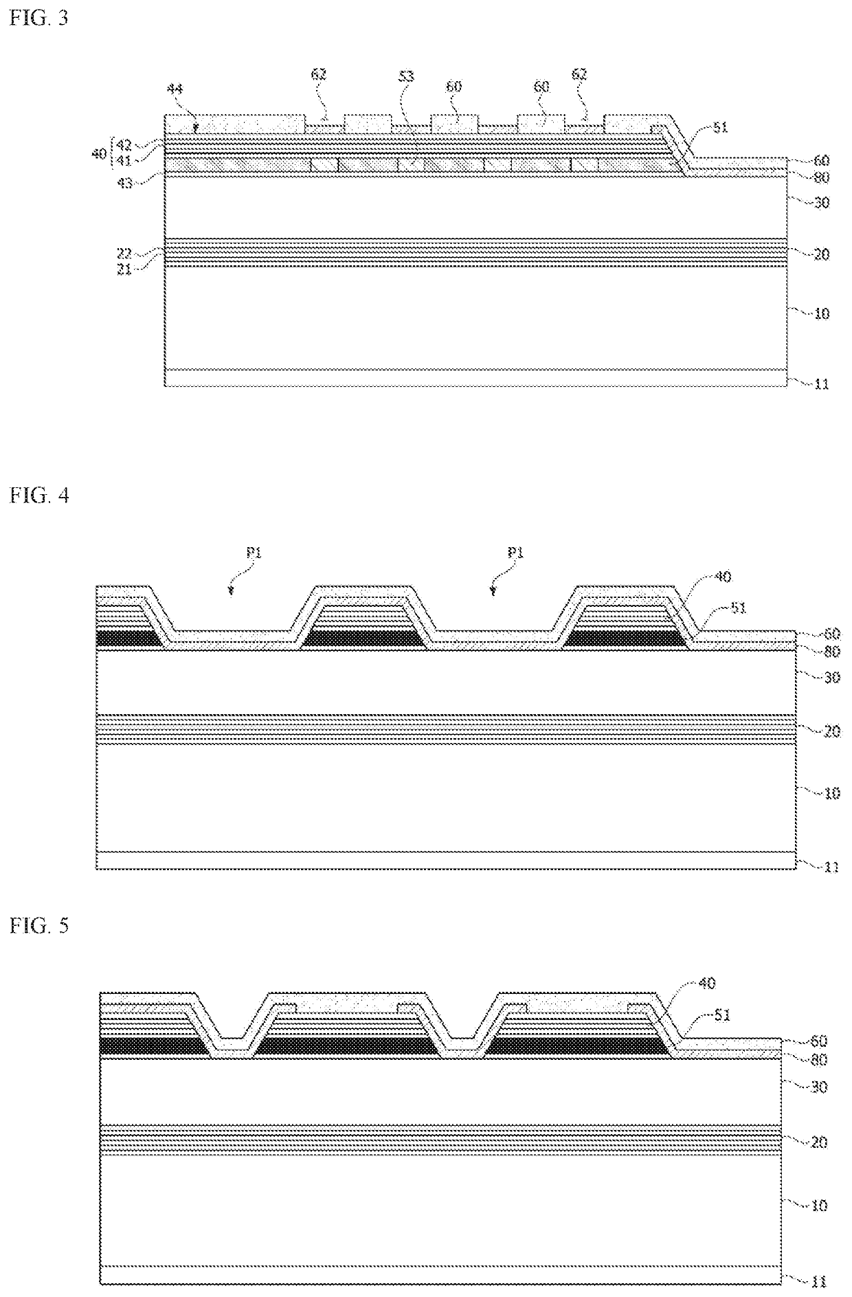
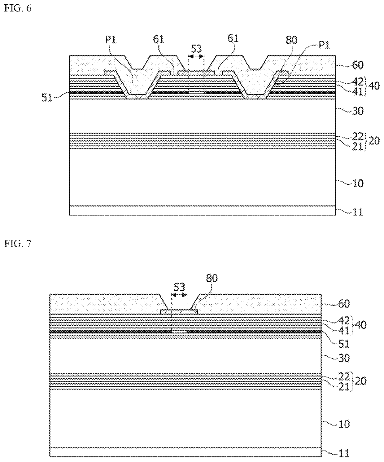
An embodiment discloses a vertical cavity surface emitting laser including a substrate, a lower reflective layer disposed on the substrate, a laser cavity including an active layer and disposed on the lower reflective layer, an oxide layer disposed on the laser cavity, an upper reflective layer disposed on the oxide layer, a plurality of first holes formed in the upper reflective layer and the oxide layer, and an upper electrode disposed on inner sides of the plurality of first holes and disposed on the upper reflective layer, wherein the oxide layer includes a plurality of light emitting regions spaced apart from each other, and the plurality of first holes are disposed to surround each of the light emitting regions in a plan view.

Description

BACKGROUND1. Field of the Invention[0001]The present invention relates to a vertical cavity surface emitting laser.2. Discussion of Related Art[0002]Vertical cavity surface emitting lasers (VCSELs) can oscillate in a single longitudinal mode in a narrow spectrum and have high coupling efficiency because a radiation angle of a beam thereof is small.[0003]Recently, studies on technologies for manufacturing light source matrixes by structuring the VCSELs in two-dimensional array forms are actively being carried out. When the light source matrixes structured in the two-dimensional array forms emit light on objects and analyze patterns of reflected light, three-dimensional images of the objects can be generated.[0004]Since photoconversion efficiency of the general VCSEL ranges from 34 to 40%, when the VCSEL operates, about 60 to 66% of power energy changes to heat. Accordingly, a temperature in the VCSEL increases, and thus light efficiency decreases significantly during a high current o...

Claims


Application Information

Patent Timeline
IPC IPC(8): H01S5/183H01S5/042
CPCH01S5/18311H01S5/04256H01S5/18361H01S5/18313H01S5/423H01S5/04252H01S5/1835H01S2301/176H01S5/02461H01S5/183H01S5/2214
Inventor CHOI, WON JINKIM, DONG HWANKIM, KEUK
Owner RAYIR CO
Learn More