
Lyophilization Promoting Element

Pending Publication Date: 2021-10-21
NAVINTA III INC
View PDF17 Cites 1 Cited by
  • Summary
  • Abstract
  • Description
  • Claims
  • Application Information

AI Technical Summary

Benefits of technology

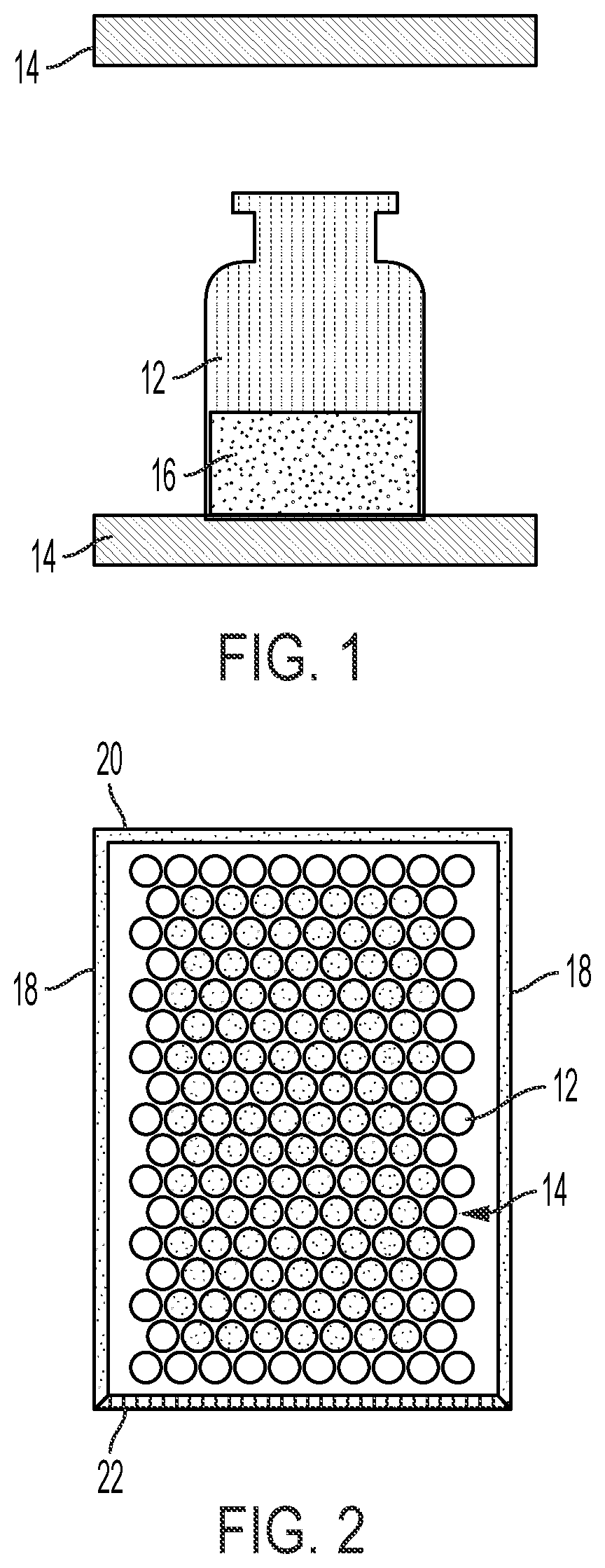
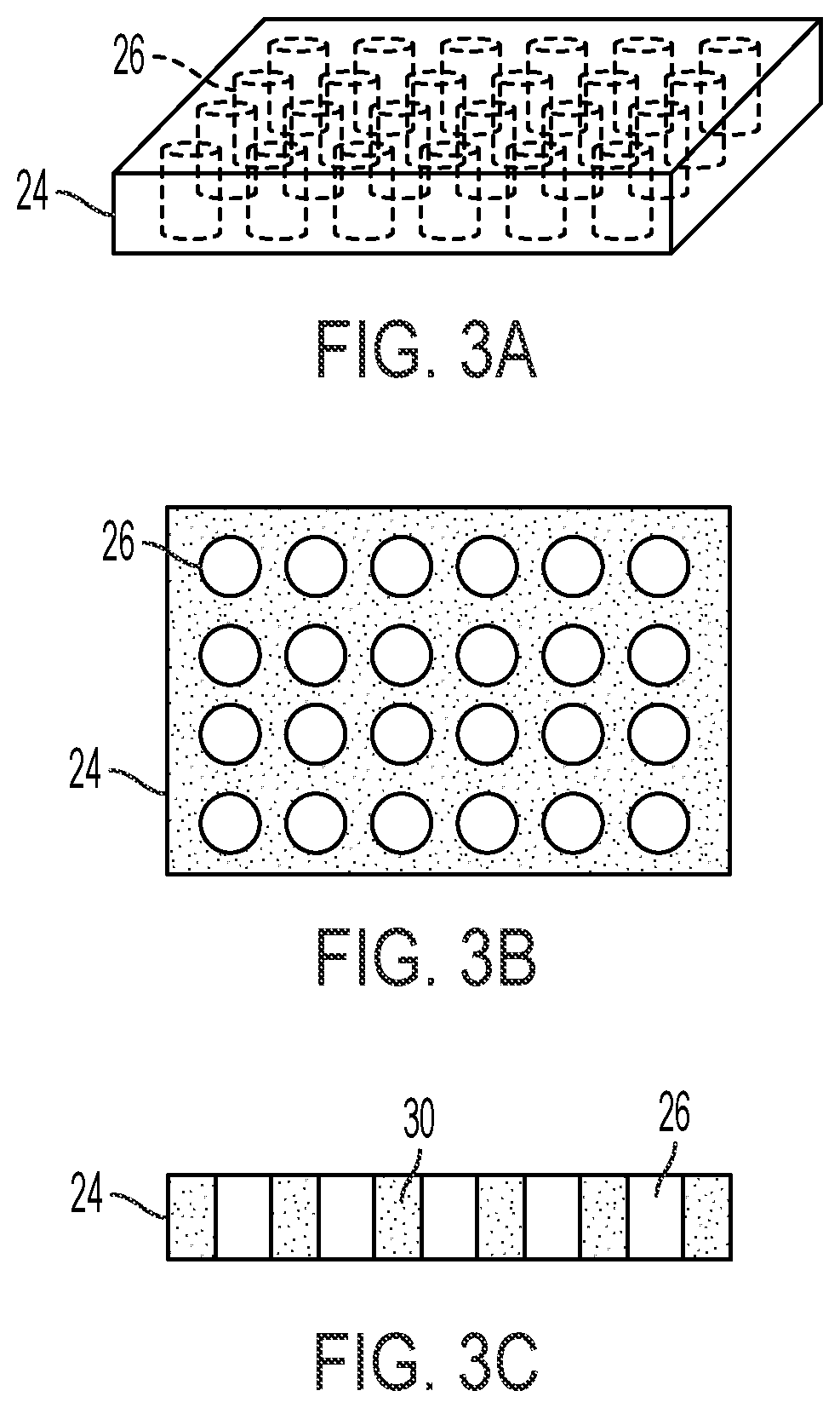
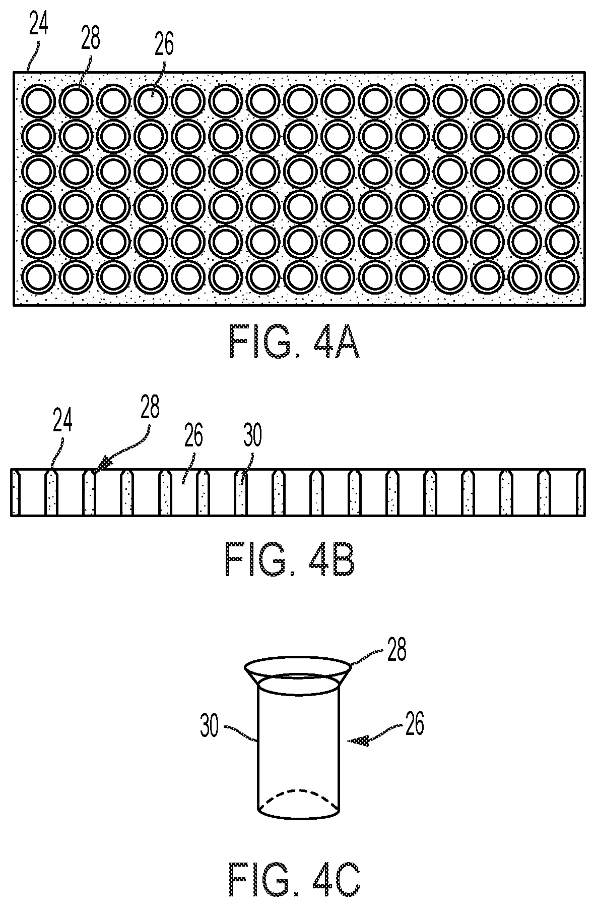
The present invention is a system and element for a pharmaceutical manufacturing process with a lyophilization step. The invention improves the lyophilization step by improving heat transfer between shelves of a lyophilizing chamber and a product container in the chamber. This is achieved by a lyophilization promoting element that facilitates the transfer of heat between a lyophilizer and the pre-lyophilization solution. The invention also reduces vial-to-vial variability in residual solvent after a lyophilization process by using an element with one or more pockets that hold a container containing a pharmaceutical solution during the process.

Problems solved by technology

This will cause faster drying or potential collapse in vials near to the door due to higher product temperature.
Thus, known issues in a lyophilization process are an inefficient or nonuniform heat transfer from shelf to vials resulting into vial to vial variability in dryness of product, and collapse or melt back of cake in some areas of lyophilizer due to higher heat exposure and higher residual solvent level due to lower heat transfer.
Vial transfer from the filling line to a lyophilizer shelf is also a challenge that ultimately impacts product yield and poses a high risk of contamination due to vial fall down and spillage of product solution online.
Moreover, tracking of an individual vial within a tray is difficult, as all vials are mixed up in the tray and it is difficult to locate the vial position on a shelf of a lyophilizer.
Another issue with product prepared by lyophilization is handling of a vial after filling and loading into lyophilizer.
As lyophilization is an aseptic operation, handling of filled and half stoppered vials is difficult and results in dropping of the vials online, which increases risk of contamination.
In current practice, location of a vial is traced by tray number and location, however, the tracking is difficult after visual inspection within a tray.
This helps with spillage and identification but is still susceptible to atypical edge vial effect.
However, if there are gaps between the metal surfaces and vial wall, heat transfer will only occur by conduction and radiation.
However, handling of the fluid cushion device is impractical for production cycles.

Method used


Image

  • Lyophilization Promoting Element
  • Lyophilization Promoting Element
  • Lyophilization Promoting Element

Examples


Embodiment Construction

[0096]Presently described herein is an efficient solution for an overall improved lyophilization process with efficient heat transfer, less vial-to-vial variation in the drying process, less risk of product spillage during transfer, and tracking of individual vial position in the lyophilizer.

[0097]The term “lyophilization” (also known as freeze-drying, lyophilisation, or cryodesiccation) means a process of removal water or other solvents by freezing a material containing water and / or other solvents followed by reducing the surrounding pressure to allow the frozen water and / or other solvents in the material to sublimate directly from the solid phase to the gas phase.

[0098]As contemplated herein, unless otherwise noted, lyophilization is meant to involve three phases: freezing, primary drying, and secondary drying.

[0099]Lyophilization is performed within a lyophilizer. A variety of lyophilizers are commercially available and known in the art. The lyophilizer will have a lyophilizing c...


PUM


Abstract

A lyophilization promoting element to facilitate the transfer of heat between a lyophilizer and a pre-lyophilization solution. The element includes a base plate with a plurality of apertures. The base plate is made of a thermally conductive material and the apertures are regularly arranged within the base plate, each aperture being sized to receive a pharmaceutical vial container containing a pre-lyophilization solution. A method of lyophilizing includes inserting one or more pharmaceutical vial containers into the plurality of apertures of the lyophilization promoting element and placing the lyophilization promoting element holding the one or more pharmaceutical vial containers on a shelf of a lyophilizer.

Description

FIELD OF THE INVENTION[0001]The present invention relates to pharmaceutical lyophilization manufacturing processes and lyophilized products. In particular, the present invention relates to a system and method of use for a lyophilization promoting element.BACKGROUND OF THE INVENTION[0002]Over the past several decades, freeze drying, or lyophilization, has become an important technology to achieve short and long term storage stability for delicate pharmaceuticals. This drying procedure is the method of choice for all active pharmaceutical ingredients (APIs) which are prone to degradation or inactivation in solution or at temperatures higher than ambient. Products such as these are typically distributed in final packaging as a lyophilized powder in a vial and with separate syringes; the powder is reconstituted with a diluent prior to administration and then injected using the syringe. The Pfizer-BioNTech COVID-19 vaccine is a recent example of a product that is manufactured using lyoph...

Claims


Application Information

Patent Timeline
IPC IPC(8): F26B5/06
CPCF26B5/06F26B25/063B01L9/06B01L7/00B01L2300/0829
Inventor PATEL, MAHENDRA R.PATEL, SANDIPKUMAR ARVINDBHAI
Owner NAVINTA III INC
Learn More