Signal Generation Device
- Summary
- Abstract
- Description
- Claims
- Application Information
AI Technical Summary
Benefits of technology
Problems solved by technology
Method used
Image
Examples
first embodiment
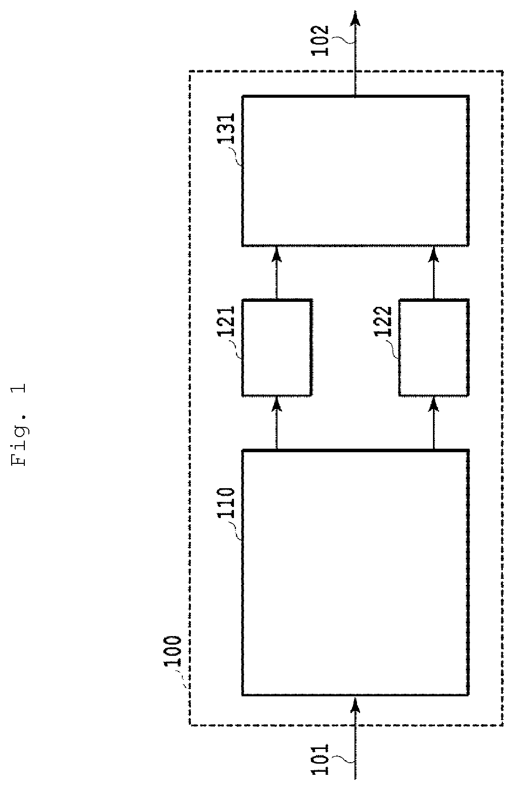
[0056]FIG. 1 is a diagram schematically showing a configuration of a signal generating device according to a first embodiment of the present invention. A signal generating device 100 is constituted by a digital signal processing unit 110 to which an input signal 101 is input, sub DACs 121 and 122, and a broadband analog signal generating unit 131 that outputs an output signal 102. When the number of sub DACs is represented by M (M is an integer equal to or greater than 2), M=2 in this example, but the operation principle can also be extended to a configuration in which M≥3.
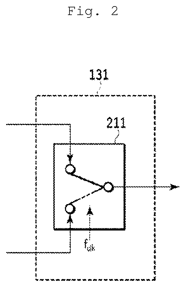
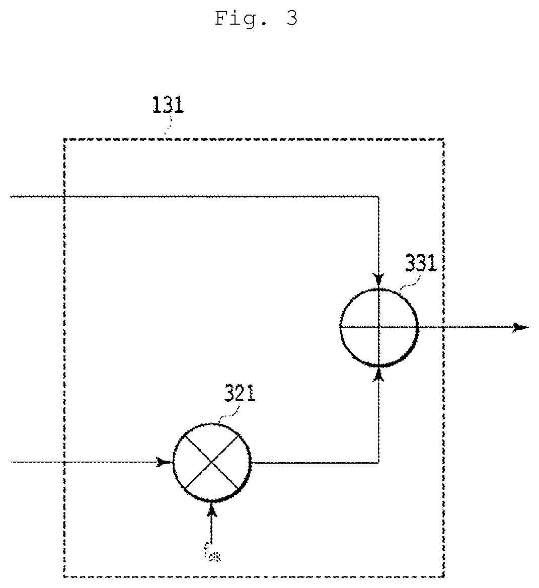
[0057]Assume that the analog bandwidth of the sub DACs 121 and 122 is fB. The broadband analog signal generating unit 131 has a function of outputting a broadband signal having a frequency range from 0 to about 2fB as the output signal 102 by generating images by shifting the frequency of each of signals input from the sub DACs 121 and 122 by an integral multiple of fB and superimposing the images.
[0058]Examples o...
second embodiment
[0117]FIG. 10 is a diagram schematically showing a configuration of a signal generating device according to a second embodiment of the present invention. A signal generating device 900 is constituted by a digital signal processing unit 910 to which an input signal 901 is input, sub DACs 921 to 923, and a broadband analog signal generating unit 931 that outputs an output signal 902. When the number of sub DACs is represented by M (M is an integer equal to or greater than 2), M=3 in this example.
[0118]Assume that the analog bandwidth of the sub DACs 921 to 923 is fB. The broadband analog signal generating unit 931 has a function of outputting a broadband signal in a frequency range from 0 to about 3fB as the output signal 902 by generating images by shifting the frequency of each of signals input from the sub DACs 921 to 923 by an integral multiple of fB and superimposing the images.
[0119]Examples of specific configurations of the broadband analog signal generating unit 931 that can b...
third embodiment
[0149]FIG. 16 is a diagram schematically showing a configuration of a signal generating device according to a third embodiment of the present invention. A signal generating device 1400 is constituted by a digital signal processing unit 1410 to which an input signal 1401 is input, sub DACs 1421 to 1424, and a broadband analog signal generating unit 1431 that outputs an output signal 1402. When the number of sub DACs is represented by M (M is an integer equal to or greater than 2), M=4 in this example.
[0150]Assume that the analog bandwidth of the sub DACs 1421 to 1424 is fB. The broadband analog signal generating unit 1431 has a function of outputting a broadband signal in a frequency range from 0 to about 4fB as the output signal 1402 by generating images by shifting the frequency of each of signals input from the sub DACs 1421 to 1424 by an integral multiple of fB and superimposing the images.
[0151]Examples of specific configurations of the broadband analog signal generating unit 14...
PUM
 Abstract
Description
Claims
Application Information
 - R&D
- Intellectual Property
- Life Sciences
- Materials
- Tech Scout
- Unparalleled Data Quality
- Higher Quality Content
- 60% Fewer Hallucinations
Browse by: Latest US Patents, China's latest patents, Technical Efficacy Thesaurus, Application Domain, Technology Topic, Popular Technical Reports.
© 2025 PatSnap. All rights reserved.Legal|Privacy policy|Modern Slavery Act Transparency Statement|Sitemap|About US| Contact US: help@patsnap.com


