
Video signal compensated amplifier for video monitoring

A video signal and video monitoring technology, which is applied in the direction of cable transmission adaptation, can solve the problems of small circuit frequency bandwidth, extra cost, poor compensation effect, etc., and achieve the effect of large circuit frequency bandwidth, good compensation effect and few components

Inactive Publication Date: 2015-05-20
SCISHINE SICHUAN
View PDF0 Cites 0 Cited by
  • Summary
  • Abstract
  • Description
  • Claims
  • Application Information

AI Technical Summary

Problems solved by technology

The current video signal compensation amplifier circuit has low compensation amplitude, small circuit bandwidth, poor compensation effect, and even uses a special compensator to increase the extra cost.

Method used


Image

  • Video signal compensated amplifier for video monitoring

Examples


Embodiment Construction

[0009] The present invention will be further described below in conjunction with accompanying drawing:

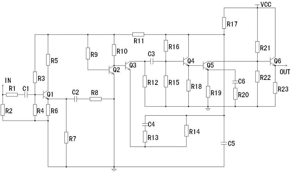
[0010] Such as figure 1 As shown, the video signal compensation amplifier for video monitoring in the present invention includes a first resistor R1, a second resistor R2, a third resistor R3, a fourth resistor R4, a fifth resistor R5, a sixth resistor R6, a seventh resistor Resistor R7, eighth resistor R8, ninth resistor R9, tenth resistor R10, eleventh resistor R11, twelfth resistor R12, thirteenth resistor R13, fourteenth resistor R14, fifteenth resistor R15, tenth resistor Sixth resistor R16, seventeenth resistor R17, eighteenth resistor R18, nineteenth resistor R19, twentieth resistor R20, twenty-first resistor R21, twenty-second resistor R22, twenty-third resistor R23, A capacitor C1, a second capacitor C2, a third capacitor C3, a fourth capacitor C4, a fifth capacitor C5, a sixth capacitor C6, a first transistor Q1, a second transistor Q2, a third transistor Q3, Th...


PUM


Abstract

The invention discloses a video signal compensated amplifier for video monitoring. The video signal compensated amplifier comprises first to twenty third resistors, first to sixth capacitors, a first triode, a second triode, a third triode, a fourth triode, a fifth triode, a sixth triode and a direct-current power source and is mainly composed of RC (resistance-capacitance) circuits. The first resistor and the first capacitor form one of the RC circuits, the eighth resistor and the second capacitor form one of the RC circuits, the twelfth resistor and the third capacitor form one of the RC circuits, the fourth capacitor, the thirteenth resistor and the fourteenth resistor form one of the RC circuits, and the sixth capacitor and the twentieth resistor form one of the RC circuits. The video signal compensated amplifier for video monitoring is simple in circuit structure, large in circuit frequency bandwidth, high reliability and good in compensation effect and has few used components. The pre-amplifier is high in compensation amplitude and available for remote transmission.

Description

technical field [0001] The invention relates to a video signal compensation amplifier for video monitoring, in particular to a video signal compensation amplifier with high compensation amplitude and good effect for video monitoring. Background technique [0002] Video surveillance usually transmits video signals over a certain distance. Video signals are generally transmitted through coaxial cables. When the transmission distance is long, the video signal will be significantly attenuated. The current video signal compensation amplifier circuit has low compensation amplitude, small circuit bandwidth, poor compensation effect, and even uses a special compensator to increase extra cost. Contents of the invention [0003] The object of the present invention is to provide a video signal compensation amplifier with high compensation amplitude and good effect for video monitoring in order to solve the above problems. [0004] The present invention achieves the above object thro...

Claims


Application Information

Patent Timeline
Patent Type & Authority Applications(China)
IPC IPC(8): H04N7/10
Inventor 张红雨
Owner SCISHINE SICHUAN
Learn More