A method of supplying injection fluid to a subsea facility

Pending Publication Date: 2021-10-07
NOV PROCESS & FLOW TECH AS
View PDF1 Cites 0 Cited by
  • Summary
  • Abstract
  • Description
  • Claims
  • Application Information

AI Technical Summary

Benefits of technology

The invention provides a method for supplying injection fluid to a subsea facility that mitigates the problem of large dead volumes in the hose. It also allows for easy refilling of large storage containers and simplifies the process of fluid injection at deep water. The mechanical protection structure can protect the storage container from impact and the invention avoids the need for large dead volume in the tubes or hoses used for filling the container. This reduces the mechanical demands on the tubes or hoses and spooling systems.

Problems solved by technology

Longer offsets, remote locations and deep-water subsea facilities contribute to make this umbilical solution undesirable, difficult and expensive.
On large water depths, this requires a long and expensive feed pipe, which may be complicated to operate.
The large dead volume in the pipe is generally undesired and may in particular be difficult when smaller container for e.g. descaler or biocides are to be filled due to increased risk of overfilling.
The main problems related to this approach are that the crane and storage container should be dimensioned to the lifting operation and that the transition of the storage container through the turbulent water zone i.e. the splash zone may be difficult in particular where the storage container in not completely filled and / or where the storage container is large.
This method in particular limits the size of the storage unit, i.e. volume and weight per tank is limited by crane and moonpool capacity.
Moreover, many small tanks may increase the number or lifting operations, which will make the method more complicated and increase the cost.
However, the method may also require long lines and there is a risk of not having the storage volume required to ensure a continuing production.

Method used


Image

  • A method of supplying injection fluid to a subsea facility
  • A method of supplying injection fluid to a subsea facility
  • A method of supplying injection fluid to a subsea facility

Examples


Embodiment Construction

[0050]The invention will now be described in further details with reference to embodiments shown in the drawing in which:

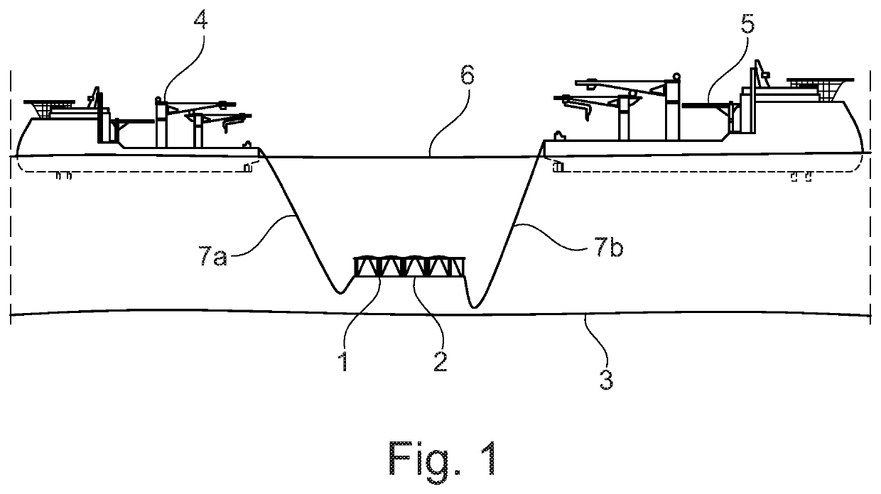
[0051]FIG. 1 shows installation of a rack with storage containers;

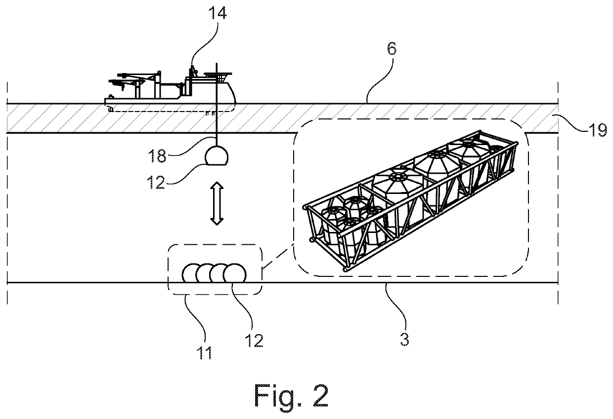
[0052]FIG. 2 shows filling of a storage container according to the invention;

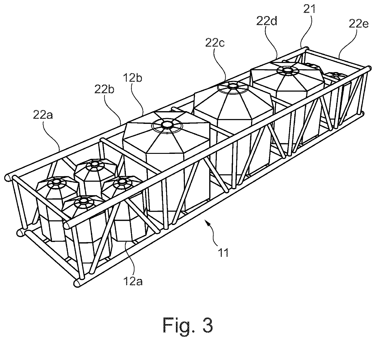
[0053]FIG. 3 shows a foundation and rack structure;

[0054]FIG. 4 shows a storage container with buoyant fluid; and

[0055]FIG. 5 shows a storage container with non-buoyant fluid.

[0056]The figures are not accurate in every detail but only sketches intended to the show the principles of the invention. Details which are not a part of the invention may have been omitted. In the figures the same reference numbers may be used for the same parts.

[0057]FIG. 1 shows the installation of a rack 1 containing a number of storage containers 2. The rack 1 is installed on the seabed 3 near a (not shown) subsea facility.

[0058]The installation of the rack 1 comprises two vessels 4, 5 floating on the sea surface 6. Each vessel is connected to th...


PUM


Abstract

A method of supplying injection fluid to a subsea facility, the method includes the step of arranging a storage container at a first subsea location, supplying the storage container with injection fluid from a surface facility, moving the storage container to a second subsea location and supplying the injection fluid from the storage container at said second subsea location to the subsea facility, wherein the second subsea location is closer to the seabed than the first subsea location. Preferably the storage container at the second subsea location is supported by the seabed.

Description

TECHNICAL FIELD[0001]The present invention generally relates to subsea supplying of injection fluids and specifically comprises a method of supplying an injection fluid to a subsea facility, such as a petroleum production subsea facility or a drilling facility.BACKGROUND[0002]Subsea drilling and petroleum production activity often require the use of injection fluids, such as mud or chemicals at or near the seabed. Historically, such injection fluid has been supplied to the point of injection via hoses, tubes or pipes bundled into “umbilicals” to supply the injection fluid from nearby surface facilities e.g. from a vessel to the respective points of injection. Longer offsets, remote locations and deep-water subsea facilities contribute to make this umbilical solution undesirable, difficult and expensive.[0003]It has been suggested to install storage container with injection fluid at the seabed nearby the point of injection. Thereby much shorter injection pipes are required for the in...

Claims


Application Information

Patent Timeline
IPC IPC(8): E21B27/02E21B43/01
CPCE21B27/02E21B43/01E21B41/0007E21B7/12
Inventor LUND, JULIEBJØRN, MARIUS
Owner NOV PROCESS & FLOW TECH AS
Why Eureka
Try Eureka