
Method For Manufacturing Metal Composite Sintered Body

a metal composite and body technology, applied in the field of metal composite sintered body manufacturing, can solve the problems of reducing workability, difficult to improve the quality of metal composite sintered body, and difficult to handle and reduce workability

Pending Publication Date: 2021-09-30
SEIKO EPSON CORP
View PDF4 Cites 0 Cited by
  • Summary
  • Abstract
  • Description
  • Claims
  • Application Information

AI Technical Summary

Benefits of technology

This patent is about a method to make a metal composite by injecting a binder into a metal powder and molding it to fit together without solvent treatment. The composite is then heated to remove the binder and sinter it. The method results in a composite with a maximum meshing point of 0.002 mm to 0.009 mm when the two parts are fitted together, and the binder content is between 2% and 20%. The technical effect is a method that allows for the efficient production of metal composites with desired properties, such as high strength and reduced density.

Problems solved by technology

However, the method for manufacturing a metal composite sintered body described in JP-A-2010-236042 has a problem that workability is likely to be lowered and it is difficult to improve quality of the metal composite sintered body.
Since a binder is removed or reduced by the degreasing treatment, the metal injection molded products are likely to be brittle, which may make it difficult to handle and reduce the workability.
Further, when the metal injection molded products become brittle, damage is likely to occur and the quality may be reduced.

Method used


Image

  • Method For Manufacturing Metal Composite Sintered Body
  • Method For Manufacturing Metal Composite Sintered Body
  • Method For Manufacturing Metal Composite Sintered Body

Examples


embodiments

1. Configuration of Metal Composite Sintered Body

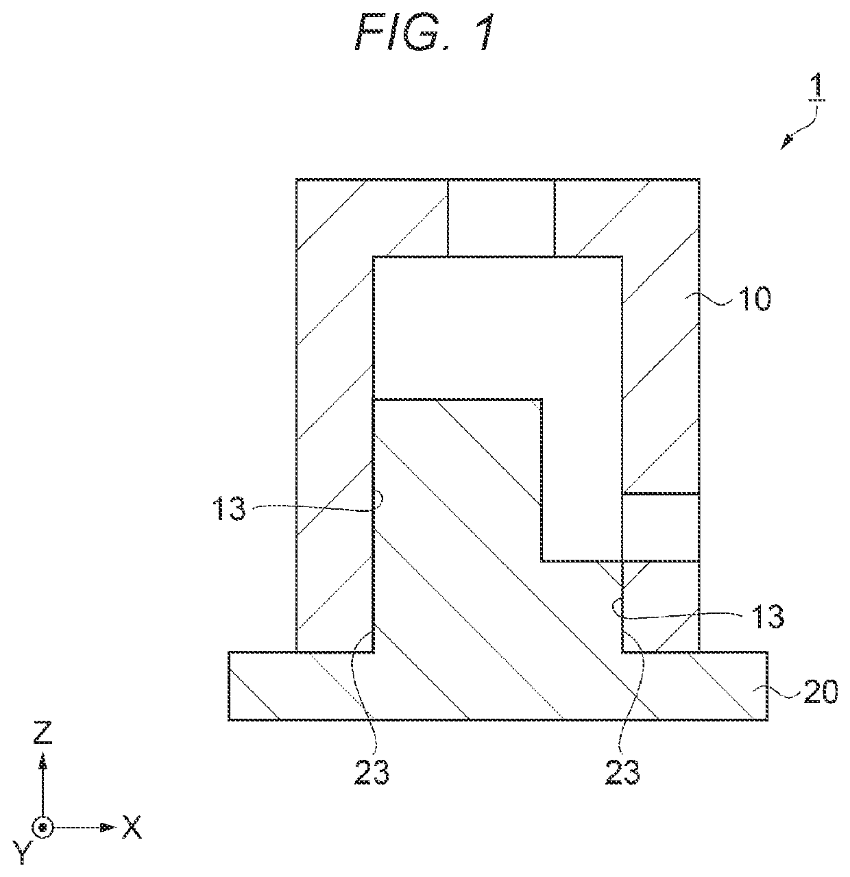
[0011]In the present embodiment, a metal composite sintered body 1 formed of two members, a first molded product and a second molded product, is illustrated. The metal composite sintered body according to the present disclosure is not limited to being formed of two members, and may be formed of three or more members. A shape of the metal composite sintered body according to the present disclosure is not limited to shapes illustrated below. Hereinafter, a configuration of the metal composite sintered body 1 according to the embodiment will be described with reference to FIG. 1.

[0012]As shown in FIG. 1, the metal composite sintered body 1 is formed by combining a first molded product 10 and a second molded product 20. The first molded product 10 has a substantially circular cylindrical shape in a plan, and has openings at a lower side, an upper side, and a side surface. The second molded product 20 is formed to have a flat lower side an...


PUM

PropertyMeasurementUnit
Temperatureaaaaaaaaaa

Abstract

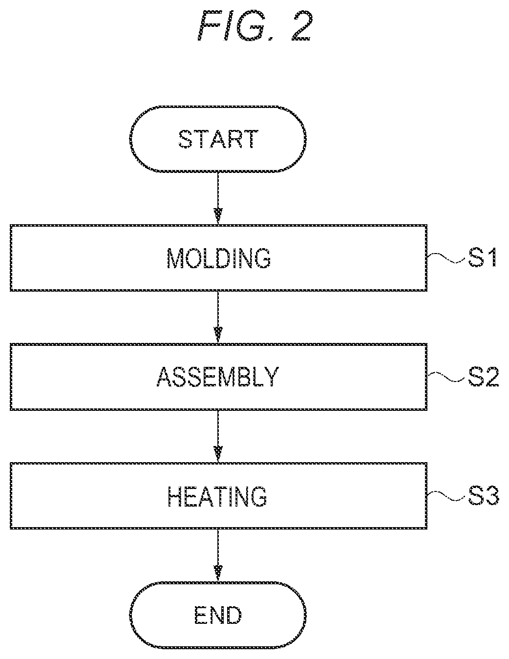
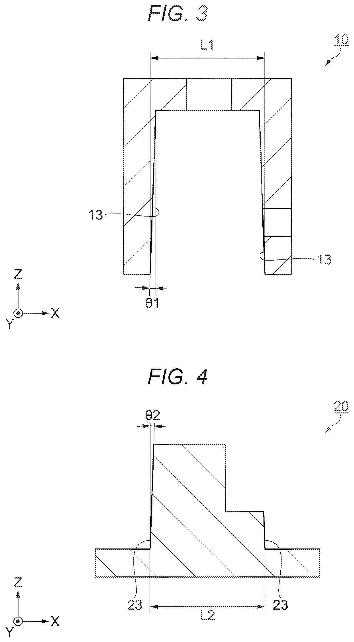
A method for manufacturing a metal composite sintered body includes: a molding step of injection-molding a first molded product and a second molded product from a kneaded product of a metal powder and a binder; an assembling step of fitting the first molded product to the second molded product without performing a solvent degreasing treatment to form a composite; and a heating step of subjecting the composite to a thermal degreasing treatment and a sintering treatment, in which the first molded product and the second molded product have fitting portions that fit to each other, at least one of the fitting portion of the first molded product and the fitting portion of the second molded product has a tapered shape, in the assembling step, a maximum meshing when the fitting portions are fitted to each other is 0.002 mm or more and 0.010 mm or less, and a content of the binder in the kneaded product is 2 mass % or more and 20 mass % or less with respect to a total amount of the kneaded product.

Description

[0001]The present application is based on, and claims priority from JP Application Serial Number 2020-059819, filed Mar. 30, 2020, the disclosure of which is hereby incorporated by reference herein in its entirety.BACKGROUND1. Technical Field[0002]The present disclosure relates to a method for manufacturing a metal composite sintered body.2. Related Art[0003]In the related art, a composite sintered body obtained by assembling a plurality of metal injection molded products is known. For example, JP-A-2010-236042 discloses a method for manufacturing a metal composite sintered body in which a plurality of metal injection molded products subjected to a degreasing treatment with a solvent are adhered and then subjected to a sintering treatment for bonding.[0004]However, the method for manufacturing a metal composite sintered body described in JP-A-2010-236042 has a problem that workability is likely to be lowered and it is difficult to improve quality of the metal composite sintered body...

Claims


Application Information

Patent Timeline
IPC IPC(8): B22F3/10B22F3/22
CPCB22F3/1017B22F3/225B22F3/1021B22F2999/00B22F2201/10B22F3/101B22F2201/01B22F2201/02B22F2201/11
Inventor MURAI, TAKAYUKI
Owner SEIKO EPSON CORP
Learn More