
Overmoulding

a technology of injection moulding and moulding parts, applied in the field of injection moulding, can solve the problems of difficult control, difficult to prove, and the article which is overmoulded can itsel

Active Publication Date: 2006-01-12
ZEPHYROS INC
View PDF99 Cites 85 Cited by
  • Summary
  • Abstract
  • Description
  • Claims
  • Application Information

AI Technical Summary

Benefits of technology

The patent describes a process where material is injected into a mold to create a layer on the surface of an article. The process includes channels that guide the material to where it is needed, and sometimes holes that allow the material to pass through the article. This results in a more precise and efficient molding process.

Problems solved by technology

This has proved extremely difficult particularly as the size of the mouldings increases.
It is also a problem when overmoulding with the structural foams used to produce structural reinforcement in automobiles such as epoxy resin and polyurethane based foams which tend to have a relatively high viscosity at the conditions under which they are injection moulded.
A further difficulty that arises with mouldings of the type previously discussed is that the article which is overmoulded can itself be formed by injection moulding and where there is a need for economic reasons to provide maximum strength with minimum use of materials such as with articles are to be used to provide structural reinforcement.
If the carrier itself is formed by injection moulding it can be difficult to control the flow of the material used to make the carrier, which can result in undesirable thick spots in the carrier at these interconnecting locations.
These can be wasteful in material and can also impair the flow of material that is overmoulded on the carrier.

Method used


Image

  • Overmoulding
  • Overmoulding
  • Overmoulding

Examples


Embodiment Construction

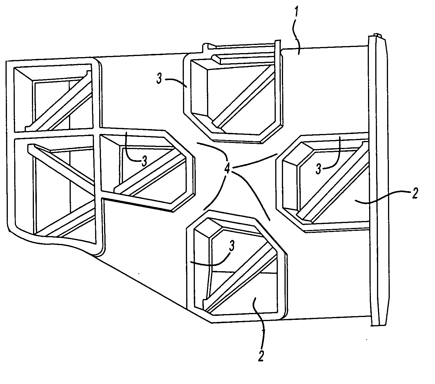
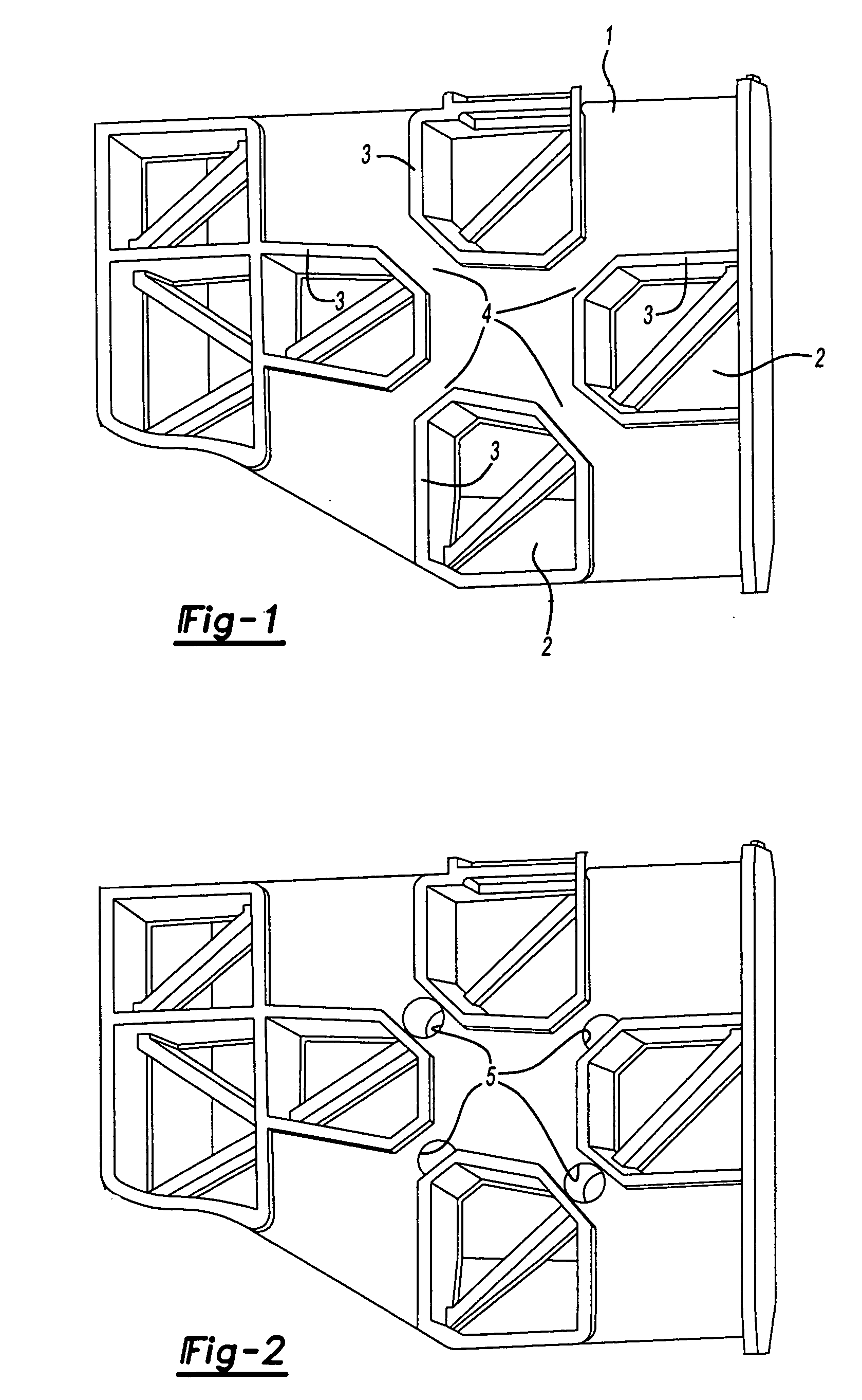
[0017] The present invention provides a process wherein a material is injection moulded to provide a layer of material over part of the surface of an article within the mould wherein channels are provided on the surface of the article to guide the material that is injected to the areas of the surface of the article where the material is to be located and wherein at least some of the channels comprise one or more holes passing through the article which enable the material being injected to pass through the article to the side remote from the position at which the material is injected into the mould.

[0018] In a further embodiment the article which is to be overmoulded has a lattice structure with interconnecting locations and channels are provided to guide the material being injected over the interconnecting locations. In a further preferred embodiment at least one of the holes is provided at an interconnecting location.

[0019] In a further embodiment of the invention in which the ar...


PUM

PropertyMeasurementUnit
temperaturesaaaaaaaaaa

Abstract

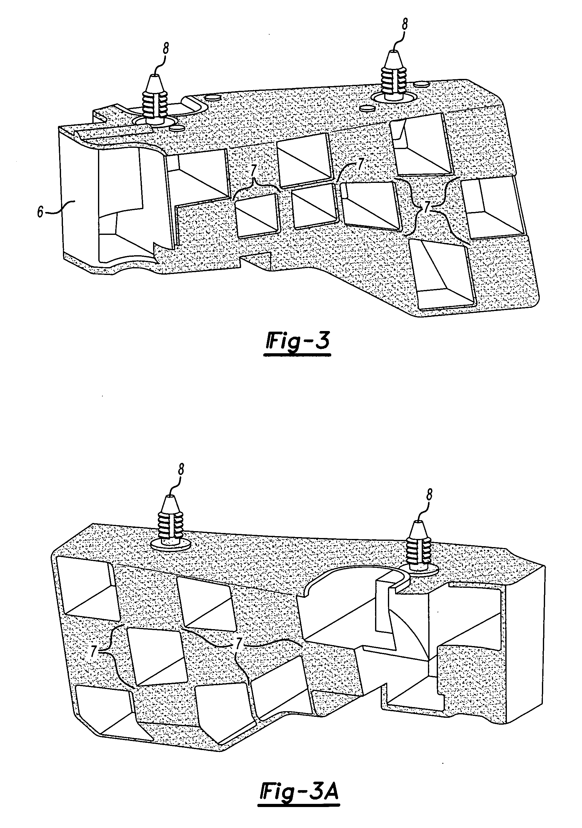
In the overmoulding of an article channels are provided in the surface of the article to guide the flow of the overmoulding material, in addition holes may be provided across the article to enable flow of the overmoulding material to the side of the carrier remote from the point of injection. The techniques are particular useful in the overmoulding of articles having a lattice or honeycomb structure particularly when produced by injection moulding. When the overmoulding material is foamable the overmoulded articles may be used as acoustic baffles or structural reinforcement for automobiles.

Description

[0001] The present application claims the benefit of the filing date of U.K. Patent Application 0413809.5 (filed Jun. 21, 2004) the contents of which are hereby incorporated by reference in their entirety. FIELD OF THE INVENTION [0002] The present invention relates to improvements in or relating to injection moulding and in particular to the production of materials by overmoulding and to articles produced thereby. BACKGROUND OF THE INVENTION [0003] Overmoulding is a technique whereby a layer of material is provided over the surface of an article by placing the already formed article in a mould and injecting the material into the mould so that it forms a layer over at least part of the surface of the article. In some instances for reasons of economy and subsequent performance of the overmoulded article it is important to be able to control the location and thickness of the overmoulded layer. Furthermore, for economy and simplicity of operation it can be desirable that the material be...

Claims


Application Information

Patent Timeline
Patent Type & Authority Applications(United States)
IPC IPC(8): B32B3/12B29C44/12B29C44/38B29C45/00B29C45/14
CPCB29C44/385B29C45/0046B29C45/14Y10T428/24149B29L2031/3005B29L2031/608B29L2031/737B29C45/14344
Inventor MUTEAU, STEHANEFAHRNER, PHILIPPE
Owner ZEPHYROS INC
Learn More