
I/q imbalance compensation

a radio transmitter and imbalance compensation technology, applied in the field of i/q imbalance compensation, can solve the problems of reducing the effectiveness of this cancellation, reducing the effectiveness of this summing, and distortion of the transmitted radio frequency signal, so as to reduce the initial mismatch

Active Publication Date: 2021-09-23
HUAWEI TECH CO LTD
View PDF1 Cites 1 Cited by
  • Summary
  • Abstract
  • Description
  • Claims
  • Application Information

AI Technical Summary

Benefits of technology

The patent text describes a method and circuit for compensating for I / Q imbalance, which is a distortion that occurs in signals transmitted through electronic devices. The method involves filtering the signals with two analog filters and then adjusting the filters to minimize the mismatch between them. The adjusted filters can be used to process the signals digitally to compensate for any residual mismatch that may be present. The technical effect of this patent is to improve the quality of signals transmitted through electronic devices by reducing I / Q imbalance.

Problems solved by technology

However, any mismatch in amplitude or phase between the tones degrades the effectiveness of this cancellation.
However, any mismatch in amplitude or phase between tones degrades the effectiveness of this summing.
This mismatch in amplitude or phase is sometimes referred to as an I / Q imbalance, and may result in distortion in the transmitted radio frequency signal.
Thus, I / Q imbalance occurs when the input signals to the frequency mixers have a range of frequencies.
The I / Q imbalance may result when there is a mismatch between counterpart components in the I-path circuitry and the Q-path circuitry.
A mismatch between counterpart components (e.g., counterpart analog filters) in the I-path circuitry and the Q-path circuitry may result in I / Q imbalance, I / Q imbalance in a radio receiver may limit the effectiveness of the design, thereby resulting in distortion.

Method used


Image

  • I/q imbalance compensation
  • I/q imbalance compensation
  • I/q imbalance compensation

Examples


Embodiment Construction

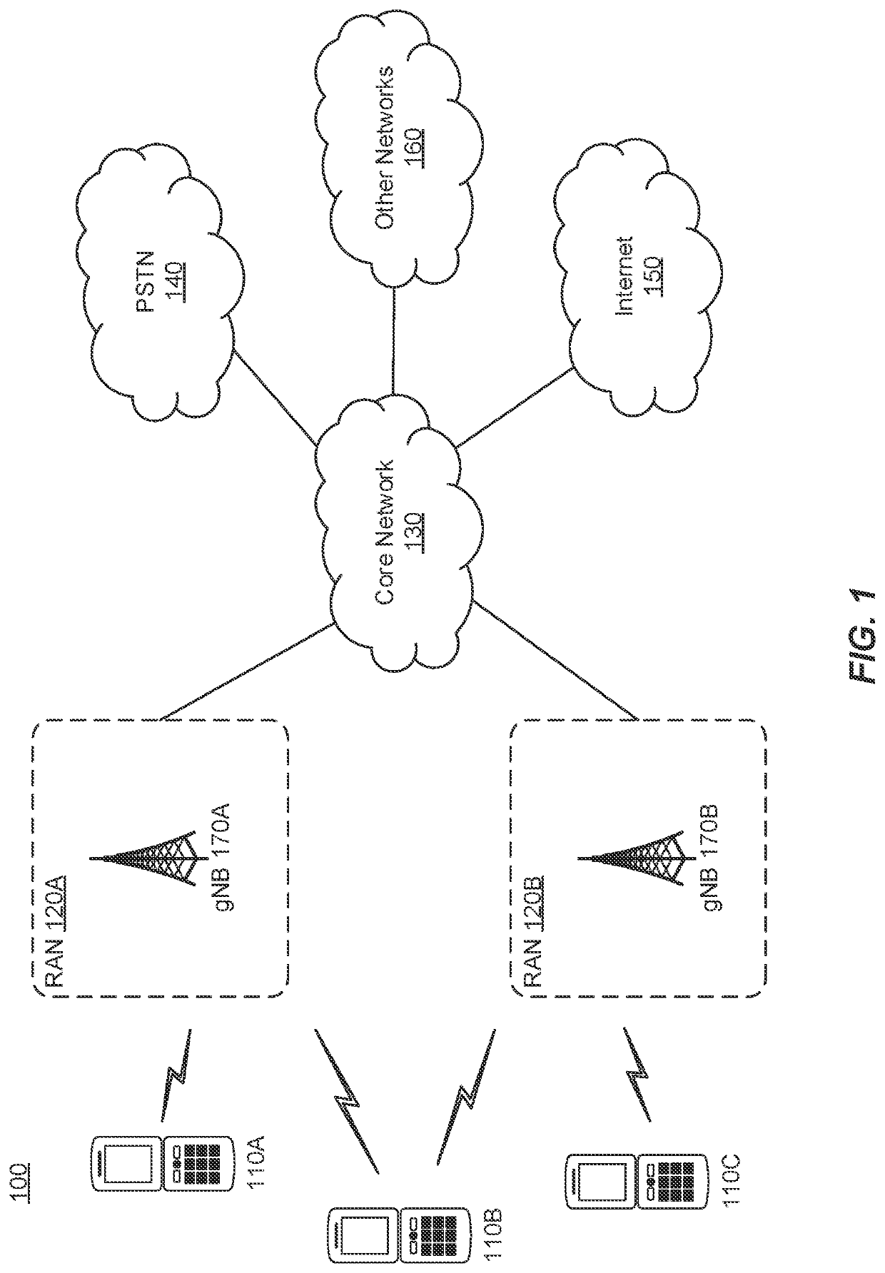
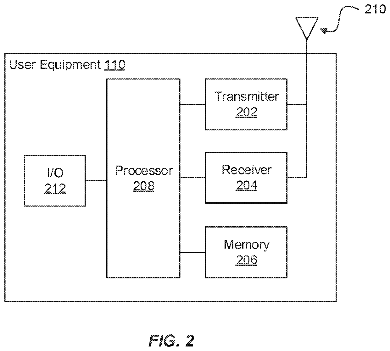
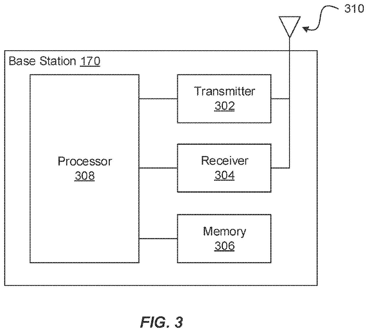
[0045]The present disclosure will now be described with reference to the figures, which in general relate to an apparatus and method for processing radio frequency signals. One embodiment includes a radio transmitter that is configured to reduce I / Q imbalance. One embodiment includes a radio receiver that is configured to reduce I / Q imbalance.

[0046]One embodiment of an apparatus has I-path circuitry having an I-path analog filter, as well as a Q-path circuitry having a Q-path analog filter. The apparatus comprises a radio transmitter, in one embodiment. The apparatus comprises a radio receiver, in one embodiment. Each analog filter may be a low pass filter. A mismatch between these analog filters may result in I / Q imbalance. Other factors can lead to I / Q imbalance. For example, a mismatch between an I-path frequency mixer and a Q-path frequency mixer can also result in I / Q imbalance. I / Q imbalance may also result if the local oscillator signals that are provided to the I-path freque...


PUM


Abstract

The disclosure relates to technology for compensating for I / Q imbalance. An apparatus includes I-path circuitry having a first analog filter configured to filter an I-path signal and Q-path circuitry having a second analog filter configured to filter a Q-path signal. An I / Q imbalance compensation circuit of the apparatus is configured to process digital versions of the I-path signal and the Q-path signal to compensate for mismatch between the I-path circuitry and the Q-path circuitry. A first circuit of the apparatus is configured to apply a coarse adjustment to at least one of the first analog filter or the second analog filter to reduce an initial mismatch between the I-path circuitry and the Q-path circuitry. The first circuit is configured to operate the I / Q imbalance compensation circuit to compensate for a residual mismatch between the I-path circuitry and the Q-path circuitry with the coarse adjustment applied.

Description

CROSS REFERENCE TO RELATED APPLICATION[0001]This application is a continuation of International Application No. PCT / CN2019 / 093107 filed on Jun. 26, 2019, which claims priority to U.S. provisional patent application Ser. No. 62 / 776,849, filed on Dec. 7, 2018 and entitled “I / Q Imbalance Compensation”, which applications are incorporated herein by reference as if reproduced in their entirety.FIELD[0002]The disclosure generally relates to correcting distortion in a radio transmitter and / or receiver.BACKGROUND[0003]A radio transmitter may have I-path circuitry and Q-path circuitry. The I-path circuitry and the Q-path circuitry may have counterpart components. For example, the I-path circuitry may have an I-path frequency mixer, whereas the Q-path circuitry may have a Q-path frequency mixer. The frequency mixers in a radio transmitter are sometimes referred to as up-mixers. The up-mixers are used to up-convert the frequency of a signal. In a radio transmitter, the I-path frequency mixer a...

Claims


Application Information

Patent Timeline
IPC IPC(8): H04L27/36H04L27/00H04L27/38
CPCH04L27/364H04L2027/0016H04L27/3863H04L27/0014H04L27/34
Inventor JIANG, HONGALQAQ, WAELZHANG, ZHIHANG
Owner HUAWEI TECH CO LTD
Learn More