
PLC silica to silicon nitride mode transformer for hybrid devices

a technology of hybrid devices and transformers, applied in the field of plc silica to silicon nitride mode transformers for hybrid devices, can solve the problems of increasing propagation losses, silicon nitride structures, and inability to permanently tune, and achieves the effects of more powerful optical devices, components and systems, and better chip yields

Pending Publication Date: 2021-09-02
BROADEX TECH +1
View PDF2 Cites 0 Cited by
  • Summary
  • Abstract
  • Description
  • Claims
  • Application Information

AI Technical Summary

Benefits of technology

The patent text talks about an opportunity to create better and more robust solutions for large integrated optical devices. This can lead to higher chip yields and the creation of more powerful optical devices, components, and systems.

Problems solved by technology

However, increasing the material contrast typically leads to drawbacks such as increasing propagation losses.
For example silica is cheap, easy to manufacture, and can be permanently tuned but the die are relatively large; whereas structures made from compounds of silicon and nitride are typically much smaller, support tight bend radii, but cannot be permanently tuned.
Silicon Nitride structures also have other drawbacks, like poor coupling to single mode fiber due to mode mismatch, polarization dependence of the waveguide index and polarization dependence of the mode field.
Another drawback of Silicon Nitride structures is higher temperature dependence of the refractive index (2.5e-5 for Si3N4 vs 0.95e-5 for SiO2).
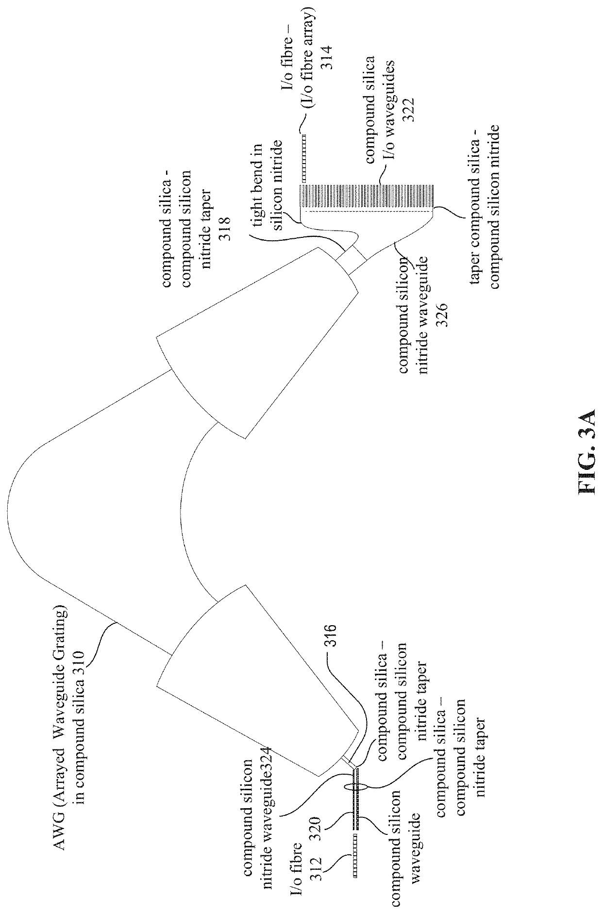
The hybrid material configurations, however, have been difficult to use in the past because it has been difficult to couple light efficiently from one technology platform e.g. silica to the other, e.g., the compound of silicon nitride.

Method used


Image

  • PLC silica to silicon nitride mode transformer for hybrid devices
  • PLC silica to silicon nitride mode transformer for hybrid devices
  • PLC silica to silicon nitride mode transformer for hybrid devices

Examples


Embodiment Construction

[0029]The following description is presented to enable any person skilled in the art to make and use the invention, and is provided in the context of a particular application and its requirements. Various modifications to the disclosed embodiments will be readily apparent to those skilled in the art, and the general principles defined herein may be applied to other embodiments and applications without departing from the spirit and scope of the present invention. Thus, the present invention is not intended to be limited to the embodiments shown, but is to be accorded the widest scope consistent with the principles and features disclosed herein.

[0030]Implementations of the invention are described herein with respect to particular applications, and it will be appreciated that the invention can be used in many other applications and environments as well.

[0031]One limitation of integrated silicon nitride based structures is that typically they experience high optical losses when coupling...


PUM

PropertyMeasurementUnit
bend radiusaaaaaaaaaa
sizeaaaaaaaaaa

Abstract

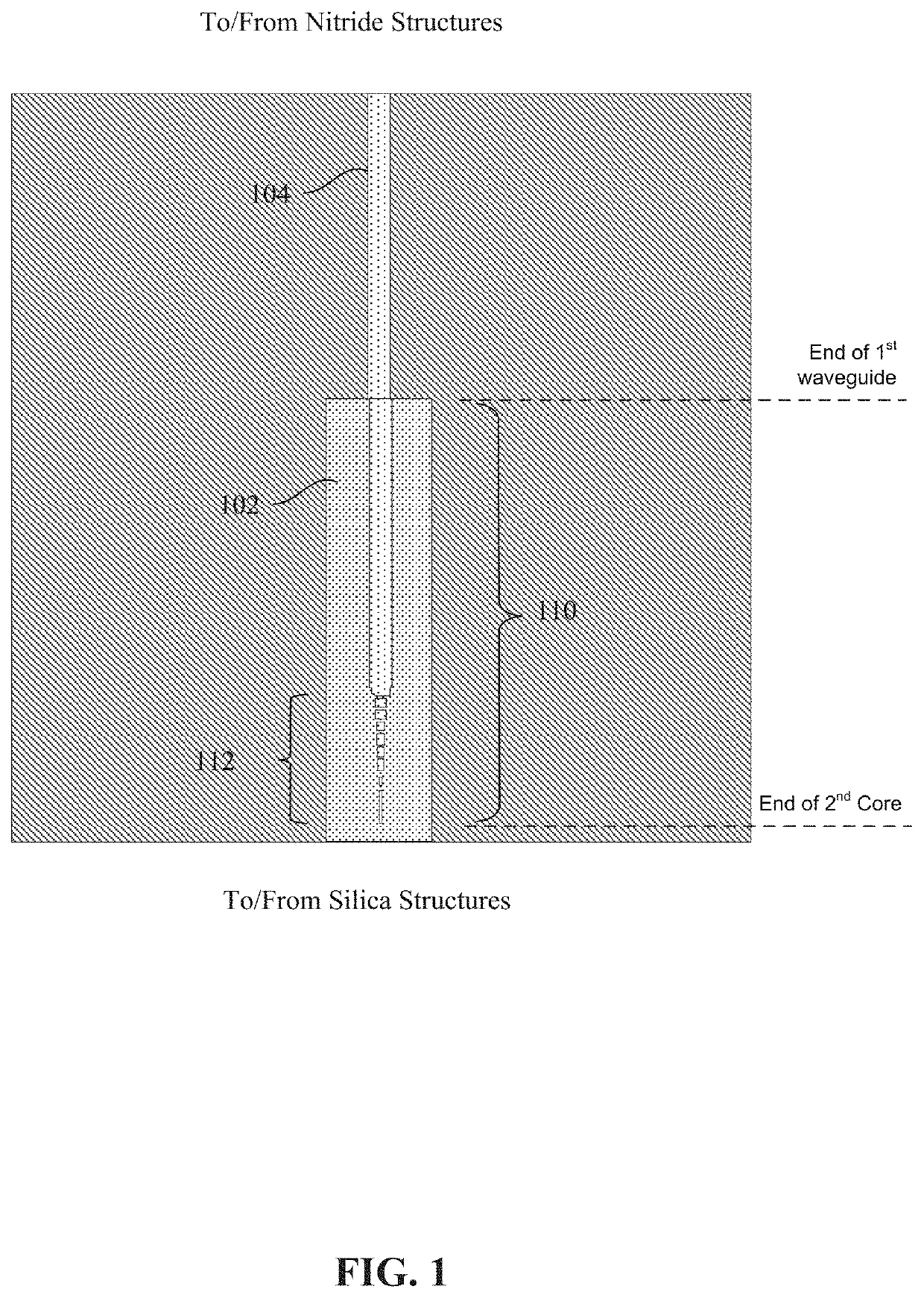
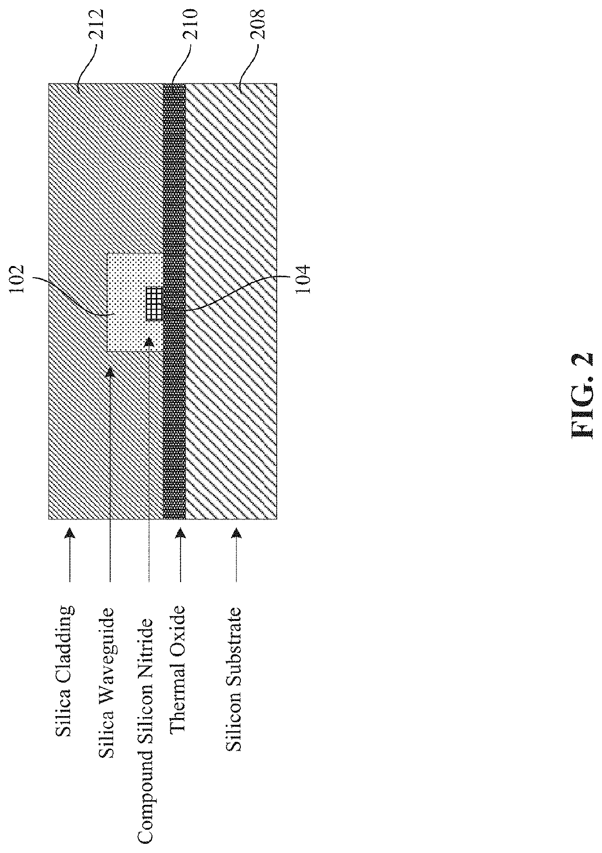
Roughly described, an optical device includes a first waveguide having a first core sheathed by a first cladding, and a second waveguide having a second core. A terminal portion of second core is disposed under a terminal portion of the first core and sheathed by the first core. The refractive index of the second core is higher than that of the first core, and the index of the first core, at least in the terminal portion of the first waveguide, is higher than that of the first cladding. The second core is structured under the terminal portion of the first core so that light traveling in the second core and directed toward the end of the second core is guided along the second core and coupled into the first core, and vice-versa.

Description

BACKGROUND[0001]This invention relates to low loss methods for interfacing silica-based optical devices with silicon-nitride-based optical devices so that each technology can be used to its best advantage in a hybrid device.DESCRIPTION OF RELATED ART[0002]The footprint of devices and optical chips needs to get smaller to make them cheaper, use less energy, dissipate less heat, reduce material waste, and reduce cost. This means that existing technologies like PLC using silica need to be developed to make the die smaller. This is usually accomplished by increasing the core / cladding index contrast. However, increasing the material contrast typically leads to drawbacks such as increasing propagation losses. An alternative approach has been to explore new materials such as Silicon Photonics, or Indium Phosphide or Silicon Nitride or Silicon Oxy-Nitride among many others. Each material base has its own trade-offs. For example silica is cheap, easy to manufacture, and can be permanently tu...

Claims


Application Information

Patent Timeline
Patent Type & Authority Applications(United States)
IPC IPC(8): G02B6/26
CPCG02B6/262G02B6/12019G02B2006/12147G02B6/1228G02B6/12002G02B6/12004G02B6/305
Inventor BULTHUIS, HINDRIKNICOL, DUNCAN P.
Owner BROADEX TECH
Learn More