
Exhaust aftertreatment system with scooped inlet

Inactive Publication Date: 2021-08-26
CNH IND AMERICA LLC
View PDF0 Cites 0 Cited by
  • Summary
  • Abstract
  • Description
  • Claims
  • Application Information

AI Technical Summary

Benefits of technology

The present invention provides an improved design for the inlet duct of an SCR canister in an exhaust system. The invention includes a scooped member that extends outward from the side of the shell body and is designed to create a turbulent flow of exhaust fluid and reductant. This turbulent flow helps to increase the mixing time of the reductant into the exhaust fluid, resulting in a more balanced fluid stream through the SCR canister. The technical effect of this design is improved exhaust-urea mixing and better overall performance of the exhaust system.

Problems solved by technology

It is difficult to adequately mix and balance the urea in the exhaust stream through parallel substrate lines for effectively meeting a desired NOx conversion rate.
Generally, the exhaust system will include a designated mixer located in the DOC; however, the mixer does not effectively mix the urea and the exhaust.
Thus, known mixers may cause lower exhaust and urea uniformity indices and an unbalanced flow.

Method used


Image

  • Exhaust aftertreatment system with scooped inlet
  • Exhaust aftertreatment system with scooped inlet
  • Exhaust aftertreatment system with scooped inlet

Examples


Embodiment Construction

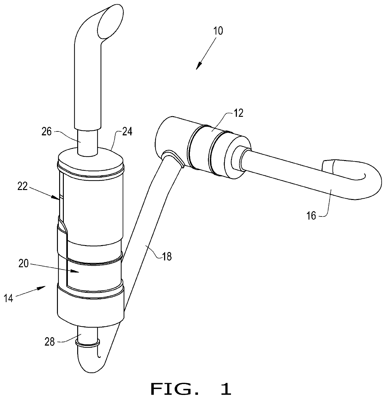
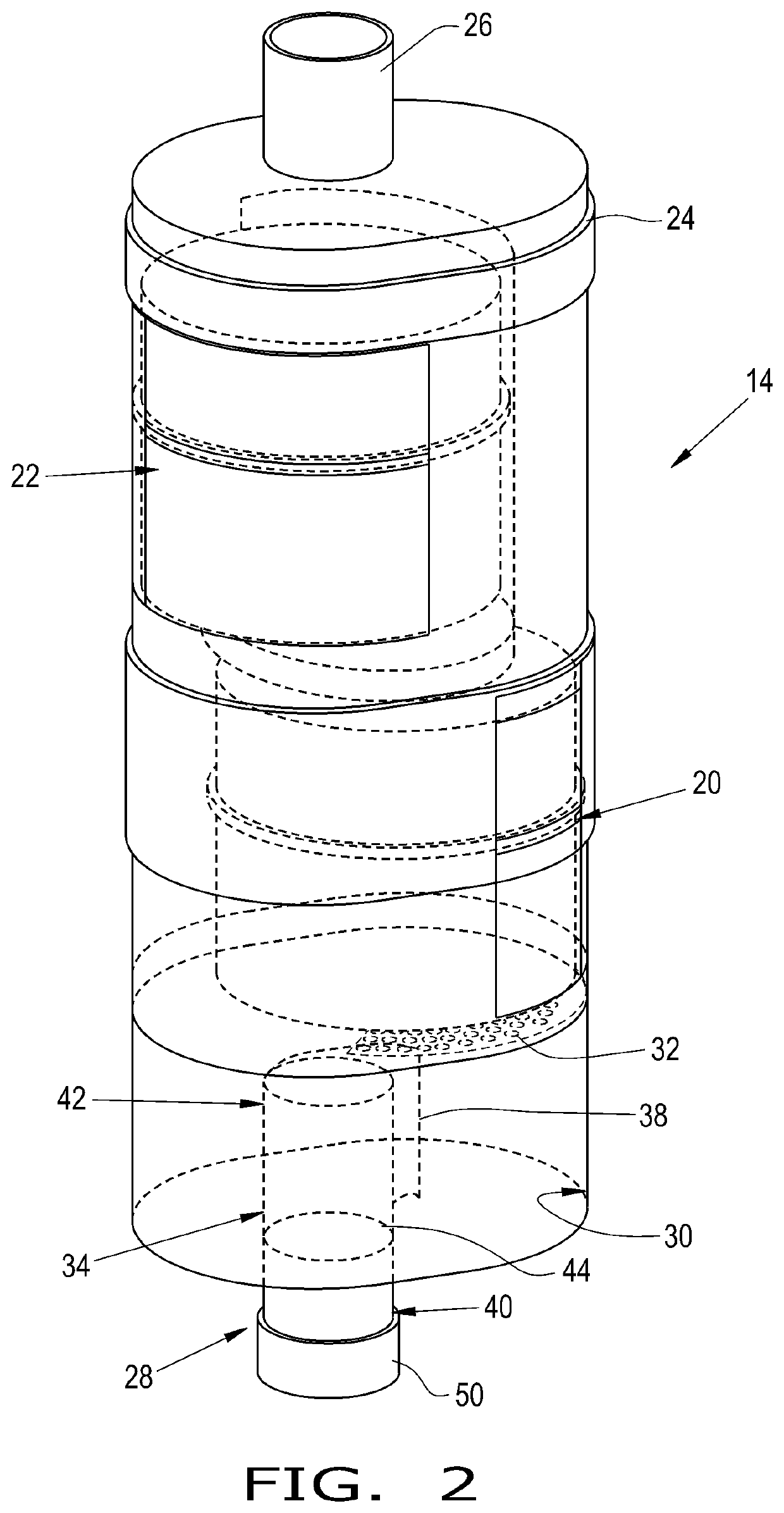
[0016]Referring now to the drawings, and more particularly to FIGS. 1-3, there is shown an exhaust system 10 of a work vehicle. The work vehicle may be in the form of any desired work vehicle such as a tractor or combine harvester. The exhaust system 10 may be configured for treating the exhaust fluid of the prime mover with a reductant, such as urea. The exhaust system generally includes a diesel oxidation catalyst (DOC) 12, a selective catalytic reduction (SCR) device or canister 14 that is downstream of the DOC 12, and various connecting exhaust ducts 16, 18. The DOC 12 may be in the form of any desired DOC 12. The SCR device 14 may generally include at least one monolith 20, 22 comprised of SCR and / or SCRoF substrates and a housing 24 for housing the monolith(s) 20, 22. The SCR device 14 may further include an outlet duct 26 and an inlet duct 28.

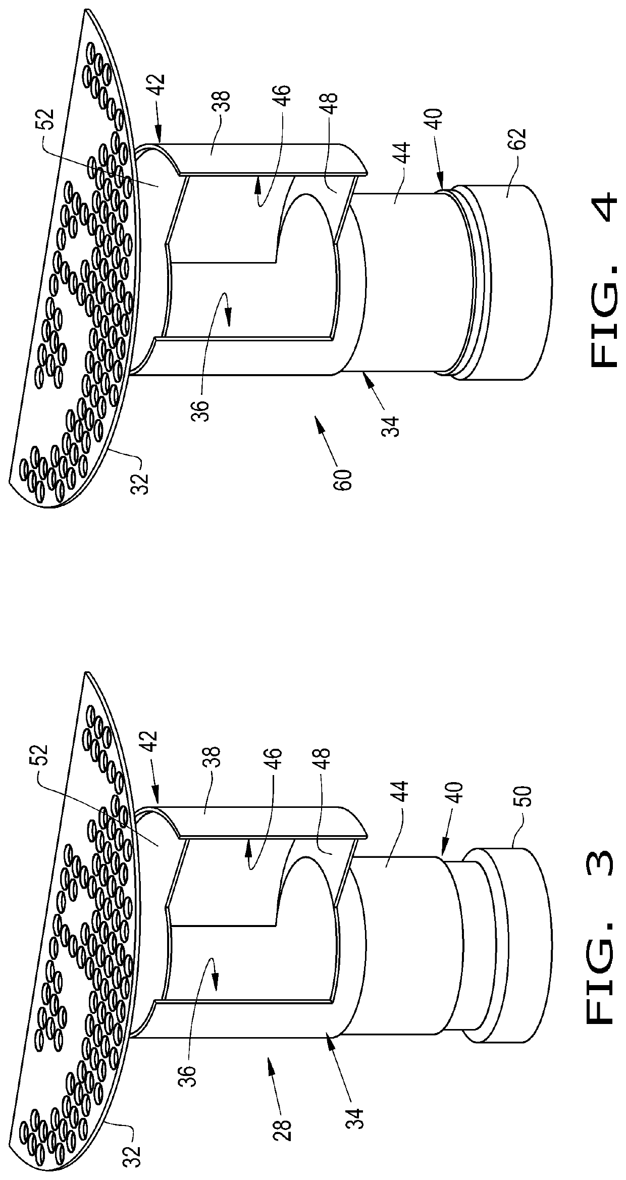
[0017]The inlet duct 28 is connected to the exhaust duct 18 and the housing 24, upstream of the monolith(s) 20, 22. The inlet duct 28 a...


PUM

PropertyMeasurementUnit
Flow rateaaaaaaaaaa
Volumeaaaaaaaaaa
Shapeaaaaaaaaaa

Abstract

An inlet duct of an exhaust system for treating an exhaust fluid with a reductant. The inlet duct includes a shell body that has a first end with a first opening therein for receiving an exhaust duct, a second end, and a side. The inlet duct also includes a chamber internally disposed within the shell body and defining a fluid passageway therethrough, and a scooped member connected to and extending outwardly from the side. The scooped member has a second opening, and the scooped member is configured for causing a turbulent fluid flow of the exhaust fluid and the reductant.

Description

BACKGROUND OF THE INVENTION[0001]The present invention pertains to agricultural work vehicles and, more specifically, to exhaust systems for agricultural work vehicles.[0002]A typical work vehicle includes a chassis, wheels and / or tracks supporting the chassis, an operator cab, a prime mover, and an exhaust system. Often, the prime mover is configured as a diesel engine to provide the necessary torque for pulling heavy equipment and / or hauling heavy loads. To comply with modern emission requirements, the exhaust system must generally include various exhaust treatment systems for reducing the level carbon dioxide (CO2), nitrous oxides (NOx), and / or diesel particulate matter (DPM).[0003]A typical exhaust treatment system has one or more aftertreatment devices, such as an exhaust gas recirculation (EGR) device, a diesel particulate filter (DPF), a selective catalytic reduction (SCR) device, or a catalytic converter, for example a diesel oxidation catalyst (DOC). A SCR device generally ...

Claims


Application Information

Patent Timeline
IPC IPC(8): F01N3/28F01N3/20B01F5/06
CPCF01N3/2892F01N3/2073F01N2610/02F01N2240/20B01F5/0616F01N2590/08F01N13/08F01N13/0097F01N13/0093F01N3/2066F01N3/035F01N3/021F01N3/103Y02T10/12B01F23/2132B01F25/4332B01F25/4521B01F25/4315
Inventor GHORPADE, KAUSHALSINGH, SAMRENDRA K.MILBURN, JR., ROWLAND J.TAMAMIDIS, PANOS
Owner CNH IND AMERICA LLC
Learn More