Stepped-louvre heating, ventilating and air conditioning unit used in high-velocity, low speed fan

a technology of heating, ventilation and air conditioning unit, which is applied in the direction of lighting and heating apparatus, liquid fuel engines, heating types, etc., can solve the problems of large areas dramatic increase in energy consumption, and large area of dead air outside the diameter of the fan blades. achieve greater airflow balance, greater airflow velocity, and greater coverage area

Active Publication Date: 2017-02-02
GO FAN YOURSELF LLC
View PDF4 Cites 11 Cited by
  • Summary
  • Abstract
  • Description
  • Claims
  • Application Information

AI Technical Summary

Benefits of technology

[0019]Another advantage of the stepped design is that it provides for a more balance airflow and greater coverage area.
[0020]Yet another advantage of the present invention is a greater velocity of airflow in the “dead area” below the centerline of the fan. In a typical fan blade design, the area directly under the hub of the fan to a distance of approximately twenty feet from the hub does not receive a significant amount of airflow. This area was known as the “dead area.” The stepped configuration of the leading edge of the present invention provides for airflow within the dead spot; that is the fan blade of the present invention has a dead spot of less than three feet.
[0021]Additionally, the design of the present invention provides the benefit of extending the effective range of air movement an additional 8-9 feet beyond the range of a fan having standard saw blades. Advantage that with a stepped leading edge, the angle of the blade can be up to 22° whereas typical HVLS fans are between 10° to 15°.
[0022]Another invention includes a manifold or diffuser to deliver air to a desired location. The manifold has an inlet and outlet whereby the outlet has one or more louvres. The louvres are adjustable to control the volume of air that is discharged from the manifold. The louvres include a stepped design along one edge of the louvre. The stepped-louvre design provides a more balanced airflow.
[0023]Another advantage of the stepped louvre is that it creates greater airflow velocity than existing louvres.
[0024]The manifold and stepped-louvre design may be utilized with a conventional fan or may be used with the stepped fan design of the present invention. The benefits of using the manifold having stepped louvres in connection with the stepped fan design are that the stepped louvres may be combined with the stepped fan blade design to distribute either heated air or chilled air in a turbulent fashion and provide for a more balanced distribution of the air. The benefits of the fan described above will also apply to the air handling manifold having stepped louvres.

Problems solved by technology

One disadvantage of traditional HVLS fans is that they have an area of “dead” air (air that has minimal air movement) in close proximity to the centerline of the fan.
Although high-speed fans provide more velocity, each unit impacts only a small, focused area.
High-speed fans are good for managing extreme heat, although they can cause a dramatic increase in energy consumption in the hot, summer months.
High-speed fans produce higher velocities in the area directly surrounding each fan, leaving large areas of dead air outside the diameter of the fan blades.
HVLS fans are virtually noiseless.
Spacing the fans too far apart will significantly diminish the system's benefits.
Despite the fact that the referred patents may present a reduction on the noise level and an increase on the efficiency, the improvement obtained is quite modest.
Consequently, the applicability of these patents is limited in actual practice.
None of the prior art shows a stepped-louvre configuration in an air handling manifold or diffuser.

Method used


Image

  • Stepped-louvre heating, ventilating and air conditioning unit used in high-velocity, low speed fan
  • Stepped-louvre heating, ventilating and air conditioning unit used in high-velocity, low speed fan
  • Stepped-louvre heating, ventilating and air conditioning unit used in high-velocity, low speed fan

Examples


Embodiment Construction

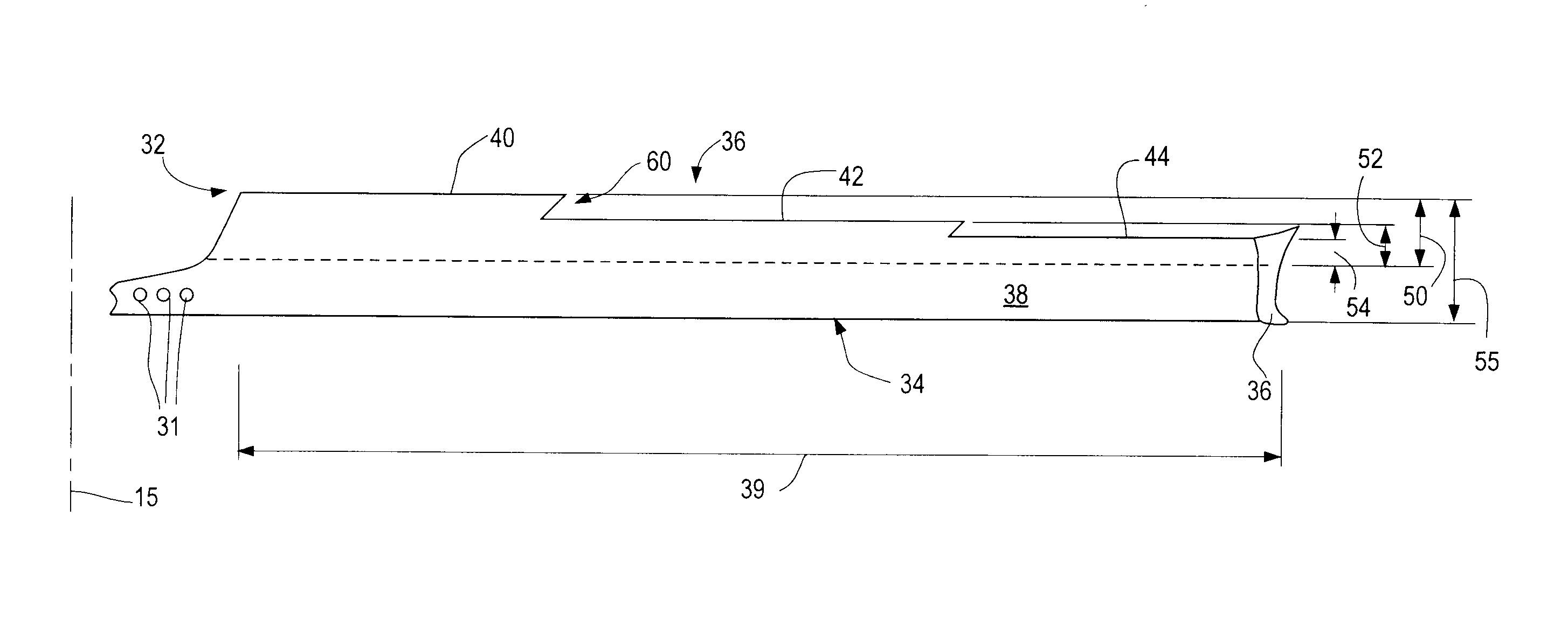
[0039]A typical high-volume, low-speed fan has between four to eight fan blades. The fan blades are typically between 4-feet to 12-feet in length and have a width of 6 inches. Thus, the total diameter of a typical fan is between 8-feet (96 inches) to 24-feet (288 inches).

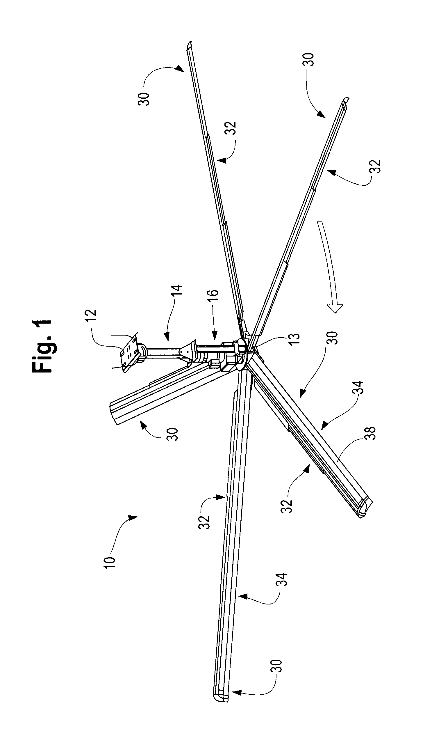
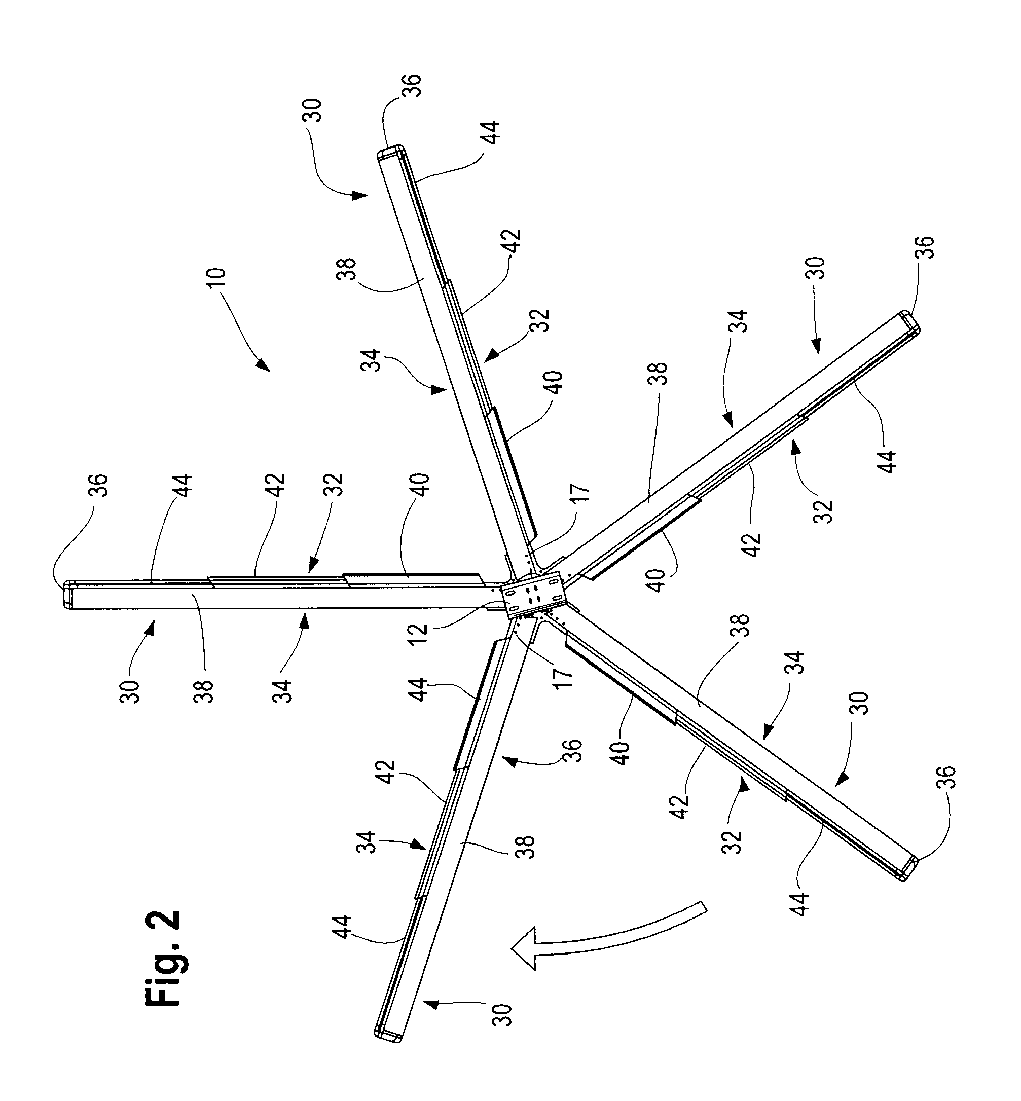
[0040]In the preferred embodiment of the present invention, as shown in FIGS. 1, 2 and 2(a), the fan 10 is mounted to a ceiling 20. The fan 10 is mounted to the ceiling 20 using a standard mount such as a universal I-Beam clamp with a swivel 12. The fan 10 may include an optional drop extension 14 that is 1 foot, 2 foot, 4 foot or more in length, depending upon the distance from the ceiling to the floor. At the end of the drop extension 14 is a gear motor 16. The motor 16 is typically an electromagnetic motor. The horsepower of the motor varies depending upon the diameter of the entire fan 18. For example, an 8-foot and 12-foot fan typically has a 1 horsepower motor 16. The 16-foot fan typically includes a 1.5 horse...


PUM


Abstract

A manifold including a stepped louvre to control airflow along a fan blade. A fan blade for use in a high-volume, low-speed fan, wherein the fan blade includes a body portion, a leading edge portion and a trailing portion. The leading edge portion of the fan blade includes a series of steps extending along the length of the leading edge. The fan distributes airflow from the manifold.

Description

[0001]This application is a Continuation-In-Part of U.S. application Ser. No. 14 / 814,161, filed Jul. 30, 2015 which is now pending and incorporated herein.FIELD OF THE INVENTION[0002]The present invention relates generally to the design of a heating, ventilating and air conditioning unit used in conjunction with high-velocity, low-speed fans. More particularly, the present invention pertains to the design of an apparatus to deliver chilled or heated air through stepped louvres of a manifold to the blades of a fan in which the leading edge has regular steps at a predetermined ratio configured to create turbulent airflow.BACKGROUND OF THE INVENTION[0003]The indoor environment is a significant concern in designing and building various structures. Human and occupant comfort are largely affected by airflow, thermal comfort and relevant temperature. Airflow is generally the measurable movement of air across a surface. Relevant temperature is the degree of thermal discomfort measured by ai...

Claims


Application Information

Patent Timeline
Patent Type & Authority Applications(United States)
IPC IPC(8): F04D25/08F04D29/02F04D25/06F04D29/54F04D29/32F04D29/38
CPCF04D25/088F04D29/325F04D29/384F04D29/544F04D29/547F04D29/023F04D25/06F04D29/522F24F3/00
Inventor NIEMIEC, DARRIN WALTERMUTH, JAMES C.WOODZICK, PATRICK TODDCARLSON, WILLIAM J.BUSKE, JEFFREY WILLIAM
Owner GO FAN YOURSELF LLC
Why Eureka
Try Eureka