Methods For Forming Flow Channels In Metal Inverse Opal Structures

a flow channel and flow channel technology, applied in the field of assembly forming, can solve the problems of increasing heat generation of electronics assemblies, increasing the operating temperature of electronics assemblies, and increasing the difficulty of thermal management of electronics assemblies, so as to improve the cooling of heat-generating devices and improve the flow of cooling fluid

Active Publication Date: 2021-08-05
TOYOTA JIDOSHA KK +1
View PDF0 Cites 0 Cited by
  • Summary
  • Abstract
  • Description
  • Claims
  • Application Information

AI Technical Summary

Benefits of technology

The present disclosure identifies a need to improve cooling of heat-generating devices in semiconductor structures and provides methods for forming flow channels in MIO structures. The methods involve positioning sacrificial spheres and heating them to fuse them together, creating a solid channel that can be removed to form the MIO structure. The MIO structure can then be used to create a flow channel through it by removing the sacrificial spheres and solid channel. This improves cooling efficiency and helps to mitigate damage to the semiconductor structure caused by excessive heat.

Problems solved by technology

As electronics assemblies are designed to operate at increased power levels to meet the increased demands of electrical systems, the electronics assemblies generate increased heat, and conventional heat sinks are increasingly insufficient to effectively lower the operating temperature of the electronics assemblies to acceptable temperature levels.
These additional layers add substantial thermal resistance to the overall assembly and make thermal management of the electronics assembly more challenging.
However, the small size of pores of conventional MIO structures may significantly restrict the flow of cooling fluid through the MIO structure, and the restricted flow of cooling fluid may prevent sufficient volume of cooling fluid from reaching desired areas of the assembly.

Method used


Image

  • Methods For Forming Flow Channels In Metal Inverse Opal Structures
  • Methods For Forming Flow Channels In Metal Inverse Opal Structures
  • Methods For Forming Flow Channels In Metal Inverse Opal Structures

Examples


Embodiment Construction

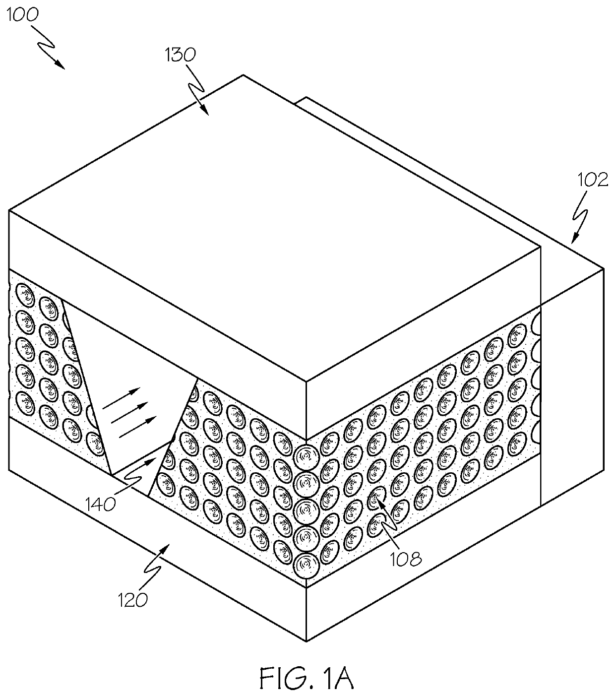
[0019]Embodiments described herein are directed to methods for forming assemblies for cooling heat-generating devices. The heat-generating devices may include, as one example, electronics modules including a power electronics device. Power electronics devices generally generate heat during operation that should be dissipated, and cooling fluid may be utilized to dissipate the heat.

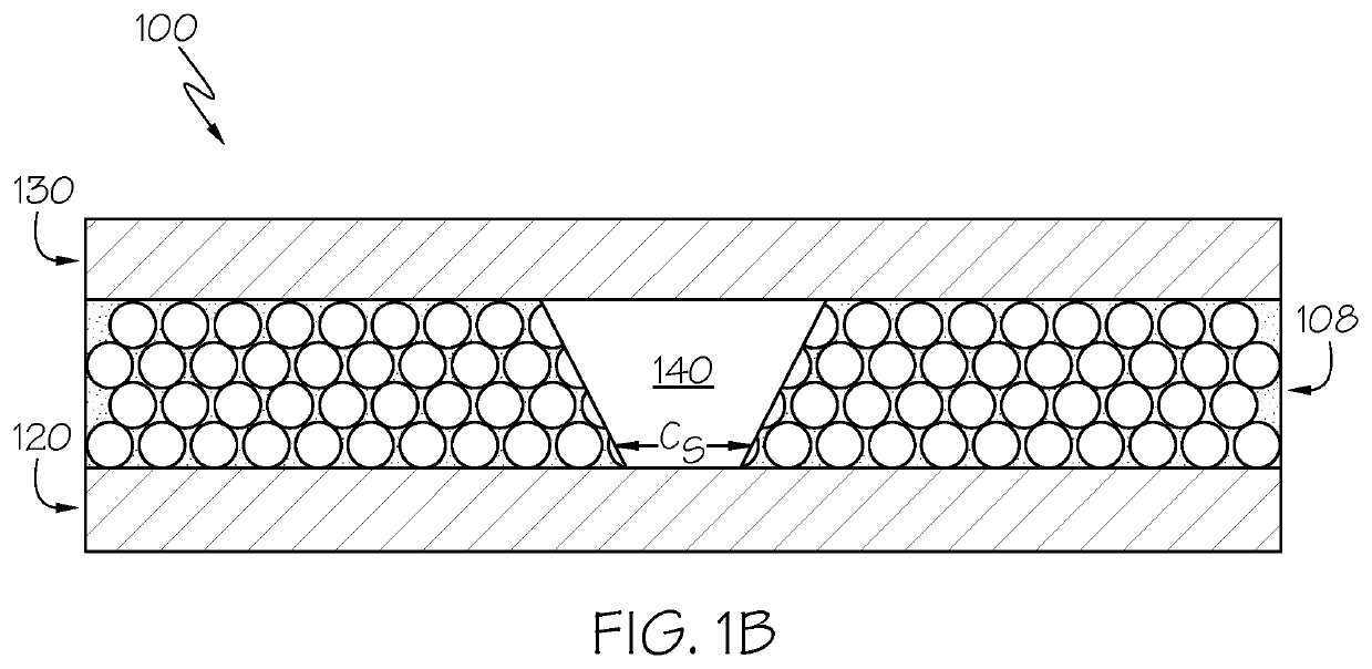
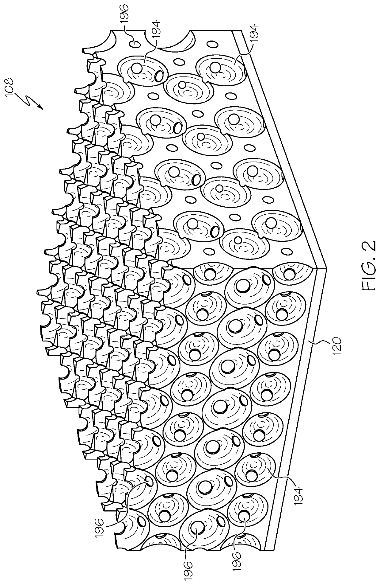
[0020]Embodiments described herein are directed to cooling assemblies including a MIO structure. One or more flow channels are formed within the MIO structure, and cooling fluid may be passed through the one or more flow channels. The one or more flow channels can increase the amount of cooling fluid that may be passed through the MIO structure, thereby increasing the amount of heat that can be dissipated from the heat-generating device. Further, in some applications, the one or more flow channels may be utilized to direct the cooling fluid through the MIO structure, for example to impinge the cooling flui...


PUM

PropertyMeasurementUnit
diameteraaaaaaaaaa
diameteraaaaaaaaaa
melting pointaaaaaaaaaa

Abstract

A method for forming a flow channel in a MIO structure includes positioning a plurality of sacrificial spheres along a base substrate, heating a region of the plurality of sacrificial spheres above a melting point of the plurality of sacrificial spheres, thereby fusing the plurality of sacrificial spheres together and forming a solid channel, electrodepositing material between the plurality of sacrificial spheres and around the solid channel, removing the plurality of sacrificial spheres to form the MIO structure, and removing the solid channel to form the flow channel extending through the MIO structure.

Description

BACKGROUNDField[0001]The present specification generally relates to methods for forming assemblies that cool heat-generating devices, and more particularly to methods for forming flow channels in metal inverse opal structures of assemblies for cooling a heat-generating devices.Technical Background[0002]As electronics assemblies are designed to operate at increased power levels to meet the increased demands of electrical systems, the electronics assemblies generate increased heat, and conventional heat sinks are increasingly insufficient to effectively lower the operating temperature of the electronics assemblies to acceptable temperature levels. Further, conventional heat sinks and cooling structures require additional bonding layers and thermal matching materials (e.g., bond layers, substrates, thermal interface materials). These additional layers add substantial thermal resistance to the overall assembly and make thermal management of the electronics assembly more challenging.[000...

Claims


Application Information

Patent Timeline
Patent Type & Authority Applications(United States)
IPC IPC(8): B82B3/00C04B38/04B82Y30/00B82Y40/00
CPCB82B3/0066C04B38/045C04B2111/00008B82Y40/00B82Y30/00C25D5/022C25D5/10C25D1/003C04B2111/40B81C1/00031B81C1/00071B81C1/00055
Inventor JOSHI, SHAILESH N.BRAUN, PAULKOHANEK, JULIASINGHAL, GAURAV
Owner TOYOTA JIDOSHA KK
Why Eureka
Try Eureka