
Laser reflow apparatus

Active Publication Date: 2021-07-22
LASERSSEL CO LTD
View PDF0 Cites 0 Cited by
  • Summary
  • Abstract
  • Description
  • Claims
  • Application Information

AI Technical Summary

Benefits of technology

The laser reflow apparatus described in this patent has several technical effects. Firstly, it allows for faster bonding of objects by using a beam transmission plate to pressurize the bonding site while emitting laser. Secondly, the laser emission unit can move to different positions on the bonding object while the beam transmission plate pressurizes it, reducing the bonding time and improving bonding quality. Thirdly, the beam transmission plate protects the bottom surface from sticking caused by laser bonding fumes, improving durability. Fourthly, a beam transmission plate transfer unit can detect pressure applied and control it to maintain the flatness between the bonding object and the beam transmission plate, reducing bonding defects. Lastly, a passage formed on the bottom surface of the beam transmission plate allows for quick discharge of fumes through suction.

Problems solved by technology

If a great number of heated heads is used, the overall price of bonding apparatus would rise considerably, and therefore, pressure-type reflow apparatus using such heated heads are usually expensive, costing at least KRW 0.8 billion to 2.5 billion.
Moreover, in the conventional methods, one head can press only one die at a time to apply pressure and heat for reflowing.
Furthermore, as laser or heat transmission is generally limited by the size of a heated head in conventional methods, a laser reflow apparatus that can use laser beams with various different sizes as a heat source is needed.
A conventional laser reflow apparatus is provided by integrally forming a pressurizing head and a laser emission unit, and thus, has a disadvantage in that the laser emission unit cannot be used once the pressurizing head is damaged.
Furthermore, in order to replace the damaged pressurizing head, the integral structure of the pressurizing head and the laser emission unit needs to be disassembled altogether, thereby causing a great waste of time for replacement.

Method used


Image

  • Laser reflow apparatus
  • Laser reflow apparatus
  • Laser reflow apparatus

Examples


Embodiment Construction

[0045]The terminology used herein is for the purpose of describing particular embodiments only and is not intended to be limiting. As used herein, the singular forms “a,”“an,” and “the” are intended to include the plural forms, including “at least one,” unless the content clearly indicates otherwise. It will be further understood that the terms “comprises,”“comprising,”“includes” and / or “including,” when used in this specification, specify the presence of stated features, integers, steps, operations, elements, and / or components, but do not preclude the presence or addition of one or more other features, integers, steps, operations, elements, components, and / or groups thereof.

[0046]Unless otherwise defined, all terms (including technical and scientific terms) used herein have the same meaning as commonly understood by one of ordinary skill in the art to which this disclosure belongs. It will be further understood that terms, such as those defined in commonly used dictionaries, should...


PUM

PropertyMeasurementUnit
Pressureaaaaaaaaaa
Heightaaaaaaaaaa

Abstract

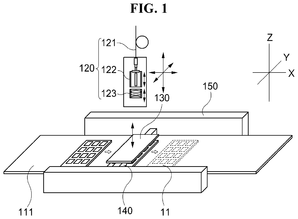
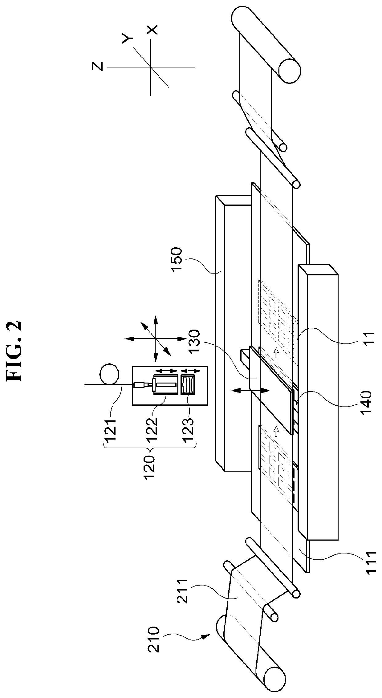
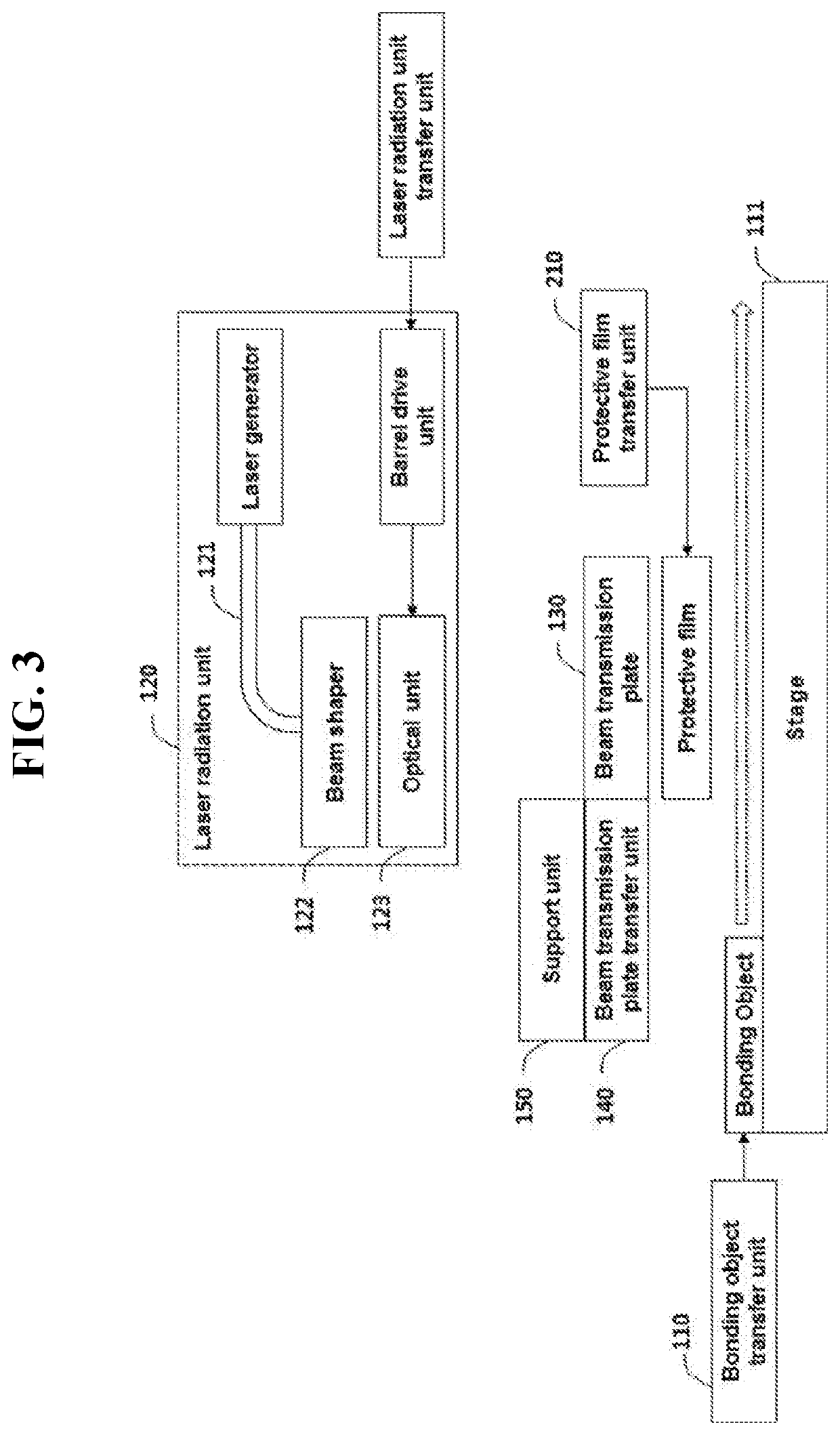
A laser reflow apparatus capable of reducing tact time for a single bonding object, and accelerating an overall bonding process for all of a plurality of bonding objects is provided. The laser reflow apparatus comprises a bonding object transfer unit including a stage, a laser emission unit, a beam transmission plate, and a beam transmission plate transfer unit.

Description

TECHNICAL FIELD[0001]Exemplary embodiments according to the invention relate to a laser reflow apparatus, and more particularly, to a laser reflow apparatus capable of reducing tact time for a single bonding object, accelerating an overall bonding process for all of a plurality of bonding objects, and accelerating a bonding process of a bonding object that needs to be pressurized due to being deposited or severely warped.BACKGROUND ART[0002]A conventional pressure-type reflow apparatus performs bonding of a thin silicon die to a substrate by brining the silicon die adjacent to a head heated to a predetermined temperature to thereby apply pressure and temperature to the die. This manner involves a one-on-one contact between the head and the silicon die, and the heat is emitted to a lower reflow portion of the silicon die by thermal conduction from the heated head. Accordingly, this type of reflow apparatus requires at least seconds or minutes of thermal conduction time.[0003]Meanwhil...

Claims


Application Information

Patent Timeline
IPC IPC(8): B23K26/06B23K26/073B23K26/08B23K26/20
CPCB23K26/0648B23K26/20B23K26/0838B23K26/0738B23K2103/56H01L21/67132H01L21/67144B23K1/0056B23K26/073B23K26/0884B23K26/16B23K26/706
Inventor CHOI, JAE JOONKIM, BYOUNG CHEOLKIM, BYUNG ROCKIM, NAM SEONG
Owner LASERSSEL CO LTD
Learn More