
Integrated physiological signal detection sensor

a physiological signal and sensor technology, applied in the field of microvibration sensor structure design, can solve the problems of inaccuracy of signal detection, inability to avoid electromagnetic interference in space and power frequency interference, inability to accurately detect data, etc., to achieve better vibration signals, facilitate wire routing, and mitigate external vibration interference

Active Publication Date: 2021-07-15
KEESON TECH CORP LTD +1
View PDF0 Cites 0 Cited by
  • Summary
  • Abstract
  • Description
  • Claims
  • Application Information

AI Technical Summary

Benefits of technology

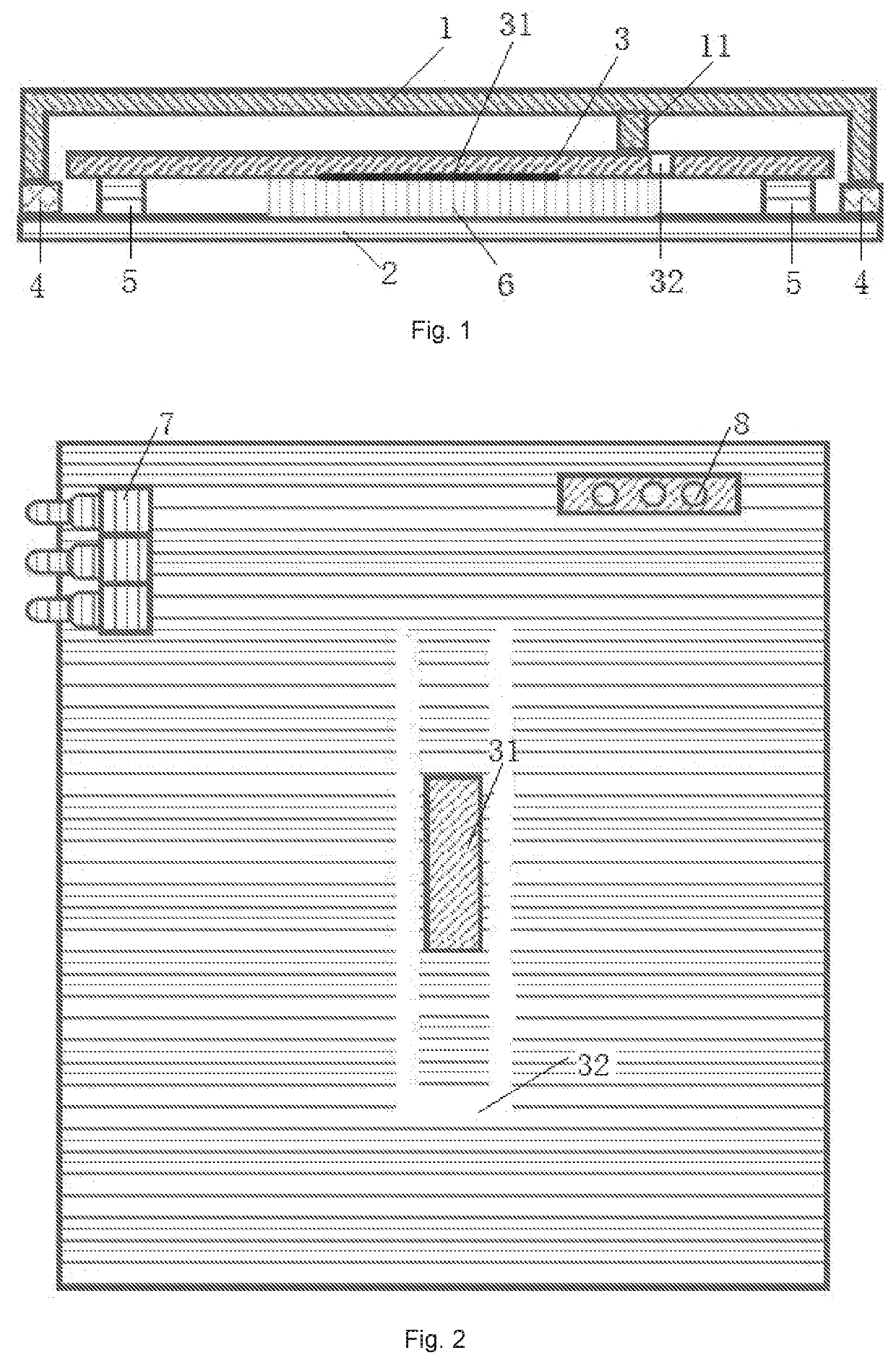
The present disclosure provides an integrated physiological signal detection sensor that simplifies sensor installation and improves signal integrity. The sensor includes a movable housing member and a fixed housing member sealed with a flexible rubber gasket and a flexible pad to mitigate interference of external vibration. The piezoelectric film is attached to the sensing unit circuit board and surrounded by a hollowed-out region on the periphery thereof, which facilitates wire routing on the circuit board. The movable housing member and the fixed housing member are both provided with a shielding layer, and the sensing circuit board is provided at an edge thereof with a POGOPIN connector which is configured to be in contact with an electrically conductive coating of the movable housing member laterally. This avoids the effect of a positive pressure applied on the movable housing member when a flexible contact piece is installed vertically on the movable housing member.

Problems solved by technology

1. A sensor is connected to a signal processing circuit board via a wire or by direct welding, and thus data collection is influenced by radiation interference caused by external connection; and moreover, an introduction of installation errors results in inaccuracy of a signal detection result.
2. Installation of most existing sensors is exposed in air without any shielding measure, and thus it is hard to avoid electromagnetic interference in space and power frequency interference.
3. A conductive wire is required for connecting a shielding layer on a housing member of an existing sensor to a shielding ground signal point or a reference signal point of a circuit board, which results in complexity in an installation process; or the reference signal point of the sensor directly abuts against a shielding layer on a surface in a movement direction of a movable housing member via an flexible piece such as an ejector pin or a spring. The flexible piece is prone to introduce direct vibration errors which results in inaccuracy of a data detection result.

Method used


Image

  • Integrated physiological signal detection sensor
  • Integrated physiological signal detection sensor

Examples


embodiment one

[0027]Embodiment One will be described in detail in combination with a view of a structure of a sensing unit circuit board schematically showed in FIG. 2. In the present embodiment, the sensing unit circuit board 3 is fixedly mounted on the fixed housing member 2 via set screw columns 5; a piezoelectric film 31 is attached to a surface of the sensing unit circuit board 3 close to the fixed housing member 2; and the piezoelectric film 31 and the fixed housing member 2 are provided therebetween with a flexible pad 6. The flexible pad 6 may mitigate vibration interference caused by action of an external pressure applied on the fixed housing member 2, so that the piezoelectric film 31 can obtain more accurate vibration signals.

[0028]In the present embodiment, the piezoelectric film 31 on the sensing unit circuit board 3 is provided with on the periphery of the piezoelectric film 31 with a rectangular hollowed-out region 32, so that a piezoelectric film region on the sensing unit circuit...

embodiment two

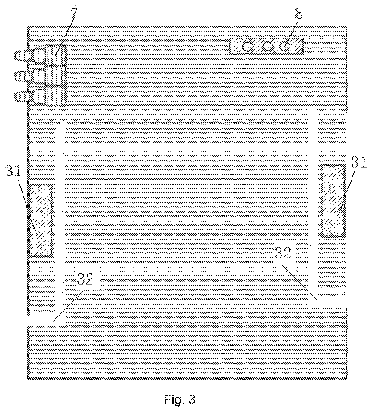
[0029]Embodiment Two will be described in detail in combination with a view of a structure of a sensing unit circuit board schematically showed in FIG. 3. In the present embodiment, the sensing unit circuit board 3 is fixedly mounted on the fixed housing member 2 via set screw columns 5; two piezoelectric films 31 are attached to a surface of the sensing unit circuit board 3 close to the movable housing member 1; and each of the piezoelectric films 31 and the fixed housing member 2 are provided therebetween with a flexible pad 6. The flexible pad 6 may mitigate vibration interference caused by action of an external pressure applied to the fixed housing member 2, so that the piezoelectric films 31 can obtain more accurate vibration signals.

[0030]In the present embodiment, each of the two piezoelectric films 31 on the sensing unit circuit board 3 is attached to an edge of the sensing unit circuit board 3, and the periphery of each of the two piezoelectric films 31 are provided with a ...


PUM


Abstract

Disclosed is an integrated physiological signal detection sensor, comprising a movable housing member, a fixed housing member, and a sensing unit circuit board. The movable housing member and the fixed housing member are connected to form an internal space therebetween. The sensing unit circuit board is fixedly installed on the fixed housing member within the space. A piezoelectric film is attached to the sensing unit circuit board. A hollowed-out region surrounds the periphery of the piezoelectric film. A protrusion is provided on the movable housing member at a position corresponding to the piezoelectric film. The sensor of the present invention has advantages of simplified sensor installation, improved signal integrity, and simplified wire routing of an electromagnetic shield layer, thereby eliminating errors caused by sensor installation and improving the accuracy of data detection.

Description

FIELD OF THE INVENTION[0001]The present disclosure relates to the technical field of micro-vibration sensor structure design, and in particular, to an integrated physiological signal detection sensor.BACKGROUND OF THE INVENTION[0002]The application principle of a piezoelectric film sensor is as follows. The piezoelectric film has characteristics such as being light, thin, soft and high in sensitivity and is very sensitive to dynamic stress, and thus it is used as a dynamic strain sensor, which is often applied in the field of physiological signal detection to convert physiologically weak vibration signals into piezoelectric signals so as to realize data collection of physiological characteristics. A relative movement of an upper cover and a lower cover of the sensor causes a fulcrum of the upper cover to press one end of a suspended beam support, so that the beam support bends downward. Since the beam support has a certain degree of hardness, uniform downward bending deformation of ...

Claims


Application Information

Patent Timeline
IPC IPC(8): G01H11/08
CPCG01H11/08A61B2562/182A61B5/6802A61B2562/02
Inventor SHAN, HUAFENGWANG, JIADONGCAO, KAIMINLI, HONGWENYU, YUAN
Owner KEESON TECH CORP LTD
Learn More