Superconducting magnet coil system

Pending Publication Date: 2021-07-08
BRUKER BIOSPIN
View PDF0 Cites 0 Cited by
  • Summary
  • Abstract
  • Description
  • Claims
  • Application Information

AI Technical Summary

Benefits of technology

This patent is about a way to use high-temperature superconducting material (HTS) in magnet systems without risking damage to the magnet. The invention involves adding a conductor in the first electrical mesh where the HTS material is connected. This conductor has a higher specific power input than the neighboring main coil section, which helps to trigger a quench and propagate it quickly through the first mesh, reducing the current there. This prevents damage to the magnet and allows for a smaller size or increased field strength. The use of Nb3Sn superconducting material in the first main coil section is recommended because it is compatible with the high field of the magnet system.

Problems solved by technology

In electrical meshes in which the quench of the superconductor is triggered only belatedly, excessive current and force increases can occur, however, which possibly overload the superconductor.
This process may be associated with high electrical voltages, currents and forces in the superconductor, which can in turn destroy the latter.
The new HTS materials place particular demands on the quench protection of a superconducting magnet, however.
What is disadvantageous in the case of a quench is, in particular, the high critical temperature of the HTS material (zero field: YBCO>80 K in contrast to the critical temperatures of conventional LTS conductors: Nb3Sn approximately 18 K, NbTi approximately 10 K), since this high critical temperature results in belated quenching if the quench starts in the NbTi or Nb3Sn part of the background magnet.
Depending on the quench protection concept, this results in an excessive current and / or force increase in the HTS section.
Moreover, the slow quench propagation in the HTS material results in local overheating, which can in turn cause burnout of the HTS conductor.
In this case, however, there is the risk of the HTS section being destroyed by the heating.
The heater tapes can also adversely affect the uniformity of the radially inner HTS winding and thus the homogeneity of the magnetic field.
The process of winding and wiring the large number of heater tapes is costly.
However, a costly and complex wiring is required for this purpose.
Furthermore, the requisite interventions in the winding pack of the section are associated with considerable risks.

Method used


Image

  • Superconducting magnet coil system
  • Superconducting magnet coil system
  • Superconducting magnet coil system

Examples


Embodiment Construction

[0012]This object is achieved according to the invention by means of a superconducting magnet coil system according to patent claim 1.

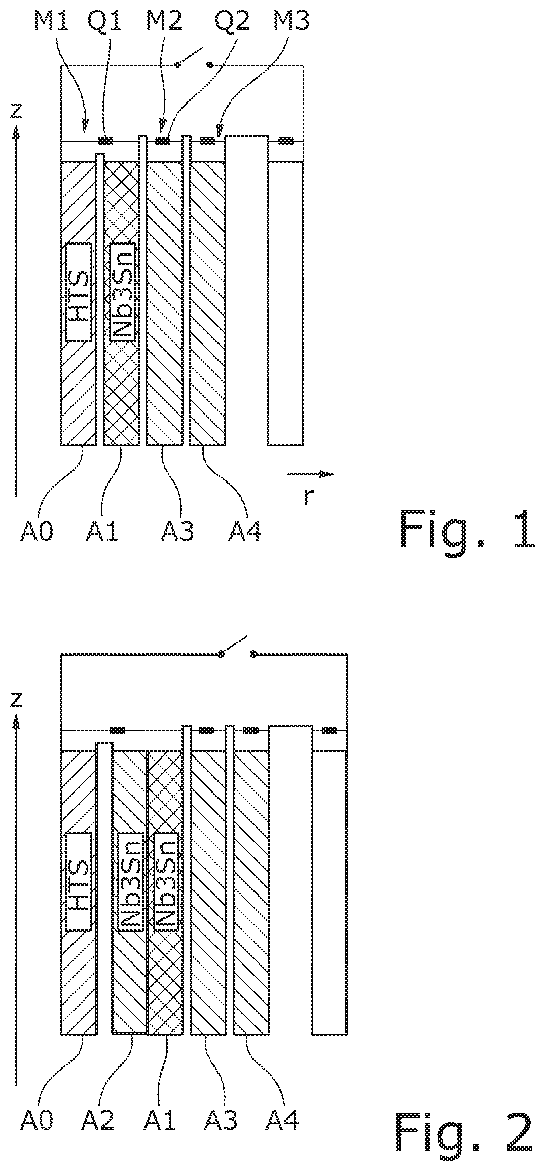
[0013]In the case of the magnet coil system according to the invention, in the case of a quench, the conductors of the main coil sections each generate a specific power input Pspec=(LT / 2π)2*1 / ρM, wherein the specific power input of the conductor of the first main coil section of the first electrical mesh is higher than the specific power input of the conductor of the neighbouring main coil section of the second electrical mesh. In this case:[0014]LT=twist length of the conductor comprising superconducting filaments,[0015]ρM=electrical resistivity of the matrix of the conductor (in a transverse direction), in which matrix the superconducting filaments are embedded (“matrix resistivity”).

[0016]The conductors of the first main coil section and of the neighbouring main coil section are thus twisted conductors, that is to say conductors whose filaments are...


PUM


Abstract

The invention relates to a superconducting magnet coil system comprising a first electrical mesh (M1) and a second electrical mesh (M2), which are interconnected in series with one another, wherein the first electrical mesh (M1) comprises in a first path an HTS (high temperature superconductor) coil section (A0) and, in series therewith, a first main coil section (A1) and in a second path a quench protection element (Q1), which bridges the series connection of HTS coil section (A0) and first main coil section (A1). The first main coil section (A1) comprises a conductor comprising superconducting filaments in a matrix. The second electrical mesh (M2) comprises a neighbouring main coil section (A3) comprising a conductor comprising superconducting filaments in a matrix. The neighbouring main coil section (A3) is that main coil section of an electrical mesh different from the first electrical mesh which, in a radial direction outwards, lies closest to the first main coil section (A1) of the first electrical mesh. The magnet coil system is characterized in that, in the case of a quench, the conductors of the main coil sections (A1, A3, A4) each generate a specific power input (LT / 2π)2*1 / ρM, wherein the specific power input of the conductor of the first main coil section (A1) of the first electrical mesh (M1) is higher than the specific power input of the conductor of the neighbouring main coil section (A3) of the second electrical mesh (M2). Consequently, using HTS superconductor material, it is possible to provide a magnet coil system with which particularly high field strengths can be generated and / or which has a small structural size.

Description

BACKGROUND OF THE INVENTION[0001]The invention relates to a superconducting magnet coil system comprising a first electrical mesh and a second electrical mesh, which are interconnected in series with one another, wherein the first electrical mesh comprises in a first path an HTS (high temperature superconductor) coil section and, in series therewith, a first main coil section and in a second path a quench protection element, which bridges the series connection of HTS coil section and first main coil section. The first main coil section comprises a conductor comprising superconducting filaments in a matrix. The second electrical mesh comprises a neighbouring main coil section comprising a conductor comprising superconducting filaments in a matrix. The neighbouring main coil section is that main coil section which, of all the main coil sections of an electrical mesh different from the first electrical mesh, in a radial direction outwards, lies closest to the first main coil section of...

Claims


Application Information

Patent Timeline
IPC IPC(8): H01F6/02H01F6/06G01R33/3815
CPCH01F6/02G01R33/3815H01F6/06H01B12/00
Inventor FRANTZ, WOLFGANGCAMINADA, RAFAELNEUBERTH, GERALD
Owner BRUKER BIOSPIN
Why Eureka
Try Eureka