
Ocular Goniometer

Pending Publication Date: 2021-07-08
UNIV DE MALAGA
View PDF0 Cites 1 Cited by
  • Summary
  • Abstract
  • Description
  • Claims
  • Application Information

AI Technical Summary

Benefits of technology

The proposed ocular goniometer solves the problem of accurately measuring the angles of a patient's eye during surgery. It is a simple and cost-effective solution that can be used in any operating room. The goniometer consists of two circular discs, one of which is fixed and marked with angles from 0° to 180°. The other disc is superimposed on the fixed disc and can rotate to choose the desired axis. It has a mechanism to move the discs forward or backward to make the marking, and once done, move away from the eye. The goniometer is disposable and not reusable, and it uses ink to make the marking. It is easy to use and can be adjusted to measure the angle of a toric lens implant. Compared to automatic systems, it is more cost-effective and portable, and it minimizes errors and annoying maneuvers for the patient. Compared to manual systems, it is more precise and efficient, making the measurement and marking more accurate.

Problems solved by technology

The problem with this device is that the scanner cannot observe the patient's eye and the angles of the reference piece marked on the outside at the same time.
This makes it impossible to measure an axis of an already implanted toric lens.
In the same way, the field of the observer is very small, in addition to not having lighting means, working in unfavorable conditions.
All this makes the maneuver uncomfortable and imprecise.
The problem with this device is that, although the scanner can inspect the maneuver, it must be done in a complex way, since it does not have a display screen.
Similarly, trial fames can be easily moved and mislead the marking.
By rotating the rods to advance the cylindrical marking piece, the desired axis can be moved, resulting in a slow maneuver, being subject to more sources of error, since lengthening the maneuver makes it easier for the patient to move the eye or move the trial frame.
Similarly, this device does not allow measuring the axis of an already implanted toric lens.
This apparatus is not designed to perform the marking in the eye but to correctly position the toric lens in a subsequent step after marking, nor does it allow measuring the axis of a toric lens already implanted toric lens.

Method used


Image

  • Ocular Goniometer
  • Ocular Goniometer
  • Ocular Goniometer

Examples


Embodiment Construction

OF EMBODIMENT OF THE INVENTION

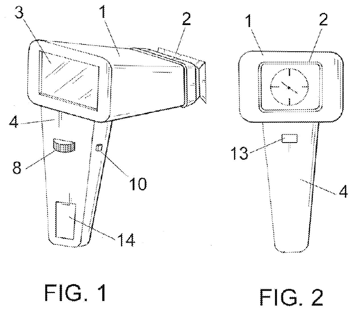
[0054]In view of the figures outlined, and especially of FIGS. 1 to 3, it can be seen how the ocular goniometer is made up of a body or casing (1) open at its ends, at whose anterior end it is established a flexible rubber piece (2) to adapt and stabilize the patient's physiognomy, while at its rear end it includes a display screen (3), ending at the bottom in a handle (4), with a series of controls.

[0055]In an ocular goniometer made according to the present invention, an axis (5) is established within the casing (1), associated with two circular discs, both transparent. The first disc (6) is fixed, and the angles from 0° to 180° are marked on it, which we will make coincide with the angles from 0° to 180° of the patient's eye. Consequently, this element neither rotates nor moves. For its part, the second disk (7) is superimposed above the first, and can rotate with respect to the first circular disc, through any conventional mechanism. The rotation of ...


PUM


Abstract

The invention relates to a goniometer that enables precise marking of the desired ocular axis in the phase immediately after surgery for the treatment of astigmatism. It essentially consists of two circular, transparent discs, one of which is at least axially stationary, in which the angles from 0° to 180° are marked, which are aligned with the angles from 0° to 180° of the patient's eye; and the other one of which is movable both angularly and axially, with a reference mark (9) and moving rigidly connected to a marking part (12), impregnated with die, which is responsible for marking the eye. Not only does the device make it possible to carry out said marking in a precise and comfortable manner, it also makes it possible to measure the angle of toric lenses already implanted.

Description

TECHNICAL FIELD[0001]The present invention refers to an ocular goniometer, the purpose of which is to perform a precise marking of the desired ocular axis in the immediate phase of the surgery for the treatment of astigmatism in the operating room with the patient seated and the head in an upright position.[0002]The device of the invention allows visualizing simultaneously the patient's eye over its entire anterior surface and the measurement angles, so that the surgeon can correctly position the device and make the 0°-180° axis of the patient's eye coinciding with that of the goniometer.[0003]Also, it can be used to measure the precise position in which the lens is placed in the postoperative period and quantify possible misalignments of the toric lens, which are responsible for the appearance of unwanted astigmatisms after surgery.[0004]Additionally, the invention can be used to measure any axis in the anterior part of the eye for any eventuality in which such a procedure is requi...

Claims


Application Information

Patent Timeline
IPC IPC(8): A61B34/20A61F2/16A61B90/00
CPCA61B34/20A61F2/1645A61B2090/3983A61B2034/2068A61B2090/3908A61B90/39A61B2017/00734A61B90/30A61B2090/395A61B2090/067A61B5/1071A61B5/6821A61B2560/0431A61B3/117A61F9/007
Inventor MARIN GRANADOS, MANUEL DDE COZAR MACIAS, OSCAR DBASCUNANA PAREJA, JUAN ANTONIOFERNANDEZ CABRERA, JOAQUINNEBRO COBOS, SALVADOR
Owner UNIV DE MALAGA
Learn More