Eureka AIR delivers breakthrough ideas for toughest innovation challenges, trusted by R&D personnel around the world.

Methods and apparatuses for emitting electrons from a hollow cathode

Active Publication Date: 2021-07-01
UNITED STATES OF AMERICA
View PDF0 Cites 1 Cited by
  • Summary
  • Abstract
  • Description
  • Claims
  • Application Information

AI Technical Summary

Benefits of technology

The patent describes a way to create a structure that can emit electrons from a hollow cathode. This structure has a plasma holding region, a gas supply source, and an orifice plate with multiple openings. The openings are designed to receive electrons from the plasma and decouple gas conductance from electrical conductance. The diameter of the openings is within a specific range. The technical effect of this invention is to provide a more efficient way to emit electrons from a hollow cathode.

Problems solved by technology

A smaller keeper orifice reduces the gas flow required to sustain the minimum pressure for ignition in either the heated or heaterless case, but also increases the resistive losses during operation by forcing the electron current to exit through a smaller diameter opening with correspondingly higher resistance.

Method used


Image

  • Methods and apparatuses for emitting electrons from a hollow cathode
  • Methods and apparatuses for emitting electrons from a hollow cathode
  • Methods and apparatuses for emitting electrons from a hollow cathode

Examples


Embodiment Construction

[0019]In accordance with example aspects described herein are hollow cathodes that include a keeper orifice that has a plurality of openings.

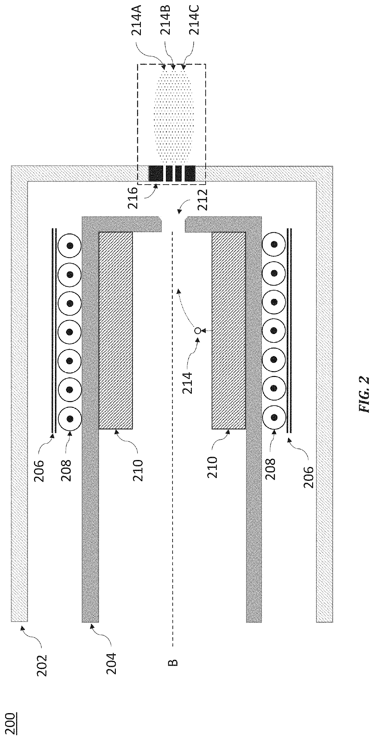
[0020]FIG. 2 is a cross-sectional view of a hollow cathode 200 according to one embodiment. A cathode tube 204 is provided which includes a cathode insert disposed on an inner periphery on the cathode tube 204 and near one end of the cathode tube 204. The cathode tube is formed of a conducting material with sufficient strength to withstand qualification for spaceflight and sufficient temperature range to withstand cathode operation. Exemplary materials meeting this requirements are graphite or a refractory metal, such as molybdenum or tantalum. However, for lower temperature emitters, stainless steel or titanium can be used. Insert 210 is the active electron emitter. As one of ordinary skill in the art will understand, the insert 210 may be made from several different materials that provide a low work function surface on an interior surface, wh...


PUM


Abstract

Methods and apparatuses for emitting electrons from a hollow cathode are provided. The cathode includes a plasma holding region configured to hold a plasma, a gas supply source configured to supply gas to the plasma holding region, and an orifice plate disposed on a periphery of the plasma holding region. The orifice plate comprises a plurality of openings constructed to receive electrons from the plasma. The plurality of openings decouple gas conductance and electrical conductance across the orifice plate. The diameters of the plurality of openings are within a range of 20%-60%, inclusive, of a diameter of a circular opening with an area equal to a sum of the areas of the plurality of openings.

Description

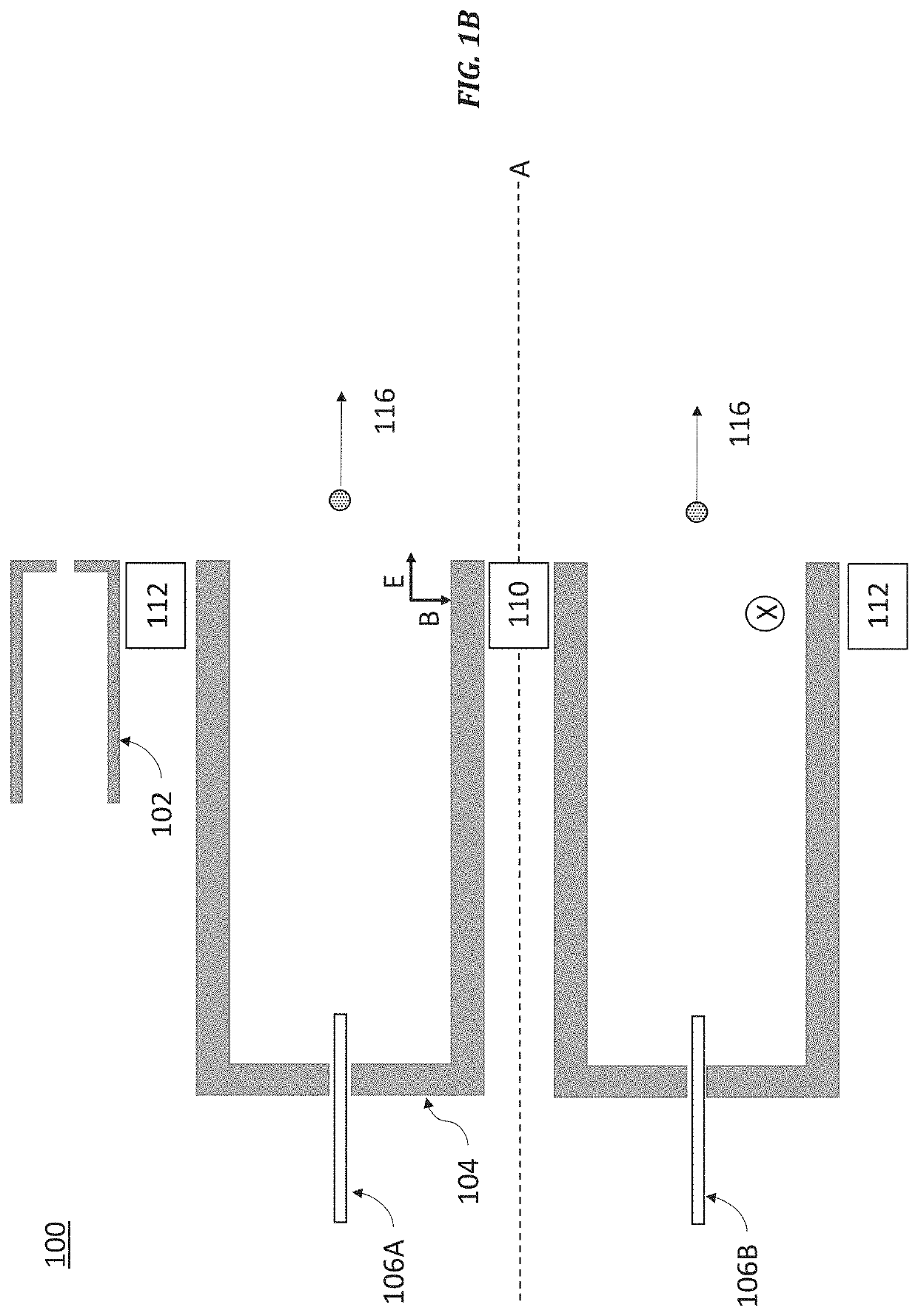
BACKGROUNDField of the Invention[0001]The present application relates generally to hollow cathodes for spacecraft propulsion systems.Description of Related Art[0002]In spacecraft propulsion, electric thrusters such as Hall thrusters and gridded ion thrusters have become increasingly popular especially for situations where a chemical based propulsion system is unfeasible or unwise. FIGS. 1A and 1B are cross-sectional views that illustrate the basic operation a Hall thruster 100 to show the role of the hollow cathode; however, the orifice plates discussed below may be used in other electric propulsion systems. A hollow cathode 102 is disposed proximate to a thrust chamber 104 formed by a dielectric insulating wall made of dielectric materials such as boron nitride, borosil, and sometimes alumina, among others. An N magnet 110 is disposed coaxially with axis A which represents the thrust center line of thruster 110. An S magnet is disposed on the periphery of wall 104 to create a magne...

Claims


Application Information

Patent Timeline
IPC IPC(8): H05H1/48
CPCH05H1/48H05H1/54H01J33/00H05H1/481H01J1/025F03H1/0025F03H1/0075
Inventor MCDONALD, MICHAEL
Owner UNITED STATES OF AMERICA
Why Eureka
Eureka Blog
Learn More