
Sealing assembly for ball valves and ball valve comprising such a sealing assembly

Active Publication Date: 2021-06-24
GASKET INT SRL
View PDF0 Cites 0 Cited by
  • Summary
  • Abstract
  • Description
  • Claims
  • Application Information

AI Technical Summary

Benefits of technology

The present invention provides a sealing assembly that solves problems of wear and fatigue by using a thermoplastic material sealing element instead of an elastomeric material insert. The sealing assembly allows for optimal sealing up to 420 bar of pressure, reducing wear and fatigue deterioration. The sealing element compensates for elastic deformation of the ball due to the pressure of the fluid, ensuring solidity and reliability in terms of deterioration and equivalent performance at low pressures. The sealing assembly also has a lower friction, resulting in a lower valve opening torque value with respect to the solution with elastomeric seal. The sealing assembly can be used in PMSS valves in which a metal-to-metal contact is provided between the front surface of the seat and the ball.

Problems solved by technology

The solutions of known type are not functionally versatile.
Indeed, currently, a seat designed for a SPE valve cannot be used in a DPE valve, and vice versa.
However, the use of the O-ring as sealing element has some drawbacks, the first of which is the risk of extrusion of the seal, i.e. in case of high working pressures, the O-ring itself is deformed and / or is partially expelled from its housing, with consequent failure cause by tearing.
In such a condition, the valve cannot ensure the tightness of the sealing.
This solution, although it improves the sealing at high temperatures, is neither entirely satisfactory in contrasting the aforesaid drawbacks (extrusion / tearing).
Although, as mentioned, the sealing elements made of elastomeric material may offer good sealing at low pressure, they appear unsuitable to work at high pressures, having a poor resistance to mechanical fatigue.
Furthermore, because of the deformity of the material of which they are made, they may be extruded from the housing in which they are accommodated.
With respect to the use of rubber O-rings or delta-rings, the thermoplastic sealing elements avoid the metal-to-metal contact between seat and ball also with high working pressures because they are less easily deformable than rubber.
On the other hand, a drawback connected to the use of thermoplastic materials is the need to have very low machining tolerances and / or misalignments in the assembly of the valve components and a very low surface roughness of the ball which must therefore be subjected to surface finishing by lapping in order to ensure good sealing.
At the same time, the sealing elements made of thermoplastic material, currently in use, are not adapted to implement good sealing at low pressure.
However, the elastomeric material undergoes major deformations during the opening operations at maximum pressure, which puts the seal in high stress conditions until causing failure by tearing.
The problem is further accentuated in the presence of aggressive environment.
Therefore, the solution which combines a thermoplastic sealing element with an elastomeric sealing element also has strong limits of reliability and durability.
Furthermore, these solutions require works which are complex for manufacturing the housings intended to accommodate the sealing rings.
In this regard, the delta-ring housing is very complex to be obtained, while the housing for the thermoplastic element requires less restrictive tolerances.
The assembly operations of the sealing assembly with two combined elements (one elastomeric and the other thermoplastic) also appear particularly complex.

Method used


Image

  • Sealing assembly for ball valves and ball valve comprising such a sealing assembly
  • Sealing assembly for ball valves and ball valve comprising such a sealing assembly
  • Sealing assembly for ball valves and ball valve comprising such a sealing assembly

Examples


Embodiment Construction

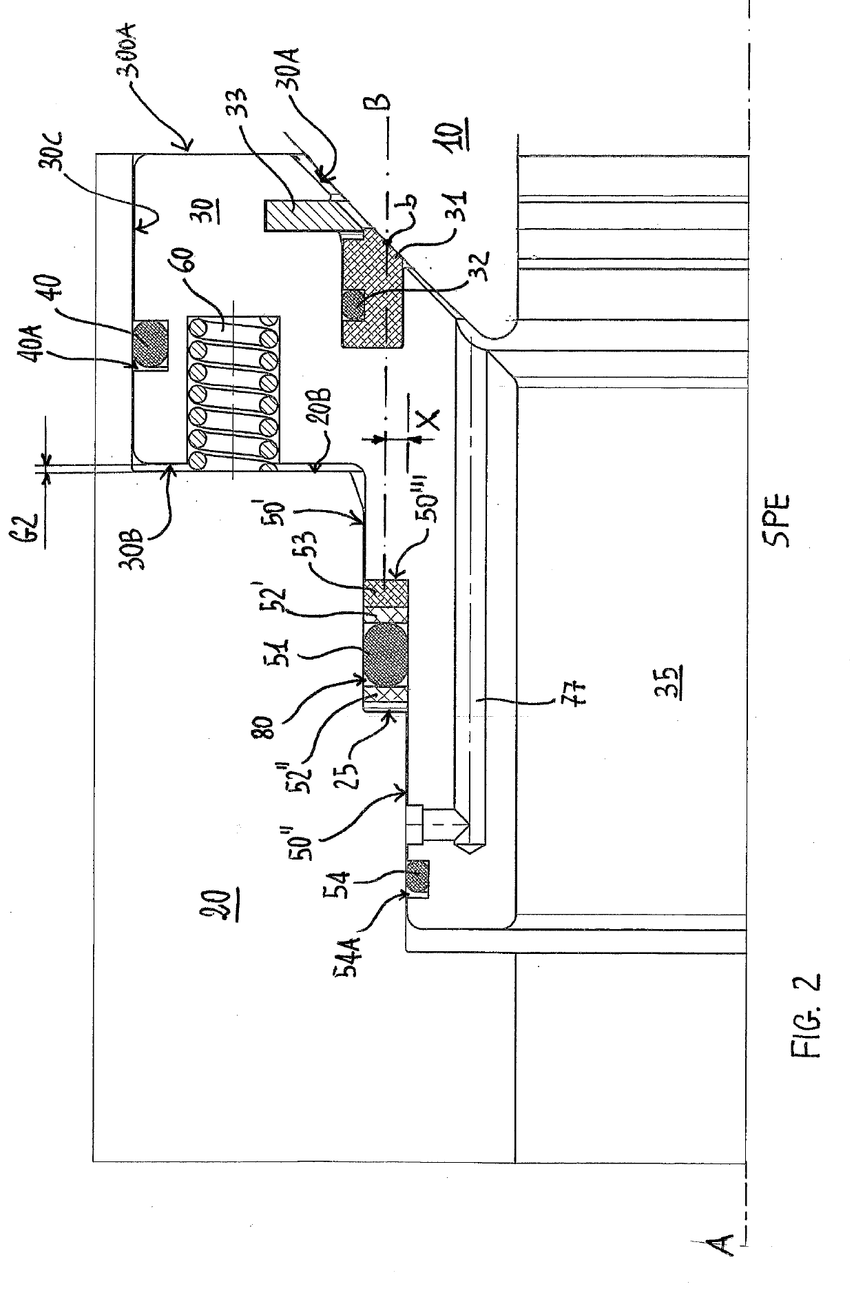
[0041]With particular reference to FIG. 1, a valve 1 of the “trunnion” type is shown, comprising a sealing assembly according to the present invention. The valve 1 is intended to be installed on a fluid pipe and comprises a body 20 which defines a housing 21, in which an internally hollow ball 10 is accommodated, which is adapted to close the fluid flow Q and create a passage gap 12 for the flow itself, as known for valves of this type. The valve 1 shown comprises a first sealing assembly 101 and a second sealing assembly 102 operatively associated with the ball 10 to achieve the fluid sealing on opposite parts of the ball 10, respectively upstream and downstream of the fluid flow inside the valve. In particular, the two systems 101,102 achieve the sealing at least when the ball 10 is in closed condition. Hereinafter in this description, reference will be made to the first sealing assembly 101 which acts upstream of the ball 10, but the same considerations also apply to the sealing ...


PUM


Abstract

The present invention relates to sealing valves used in the petroleum and gas extraction industry, in particular but not exclusively, to medium- or high-pressure ball valves. In particular, the present invention relates to a sealing assembly (101, 102) for ball valves (1), and to a ball valve comprising such an improved sealing assembly. The sealing assembly ensures excellent sealing performance at low and high pressures by exclusively using a thermoplastic material sealing element (31), thus completely eliminating the drawbacks which afflict the sealing system of known type, in particular in relation to the reliability of the sealing elements made of elastomeric material.

Description

CROSS REFERENCE TO RELATED APPLICATION(S)[0001]The present application claims priority to PCT International Application No. PCT / IB2017 / 050946 filed on Feb. 20, 2017, which application claims priority to Italian Patent Application Nos. 102106000016879 and 102016000016922 both filed Feb. 18, 2016, the entirety of the disclosures of which are expressly incorporated herein by reference.STATEMENT RE: FEDERALLY SPONSORED RESEARCH / DEVELOPMENT[0002]Not Applicable.FIELD OF THE INVENTION[0003]The present invention relates to sealing valves used in the petroleum and natural gas extraction industry, in particular but not exclusively ball valves for applications in which the pressure is comprised in a range between 0 and 450 Bar. In particular, the present invention relates to an improved sealing assembly for ball valves, preferably for valves of the “trunnion” type, and to a ball valve comprising such an improved sealing assembly.BACKGROUND ART[0004]In the petroleum and natural gas extraction i...

Claims


Application Information

Patent Timeline
IPC IPC(8): F16K5/06F16K5/20
CPCF16K5/0663F16K5/205F16K5/0678F16K5/06
Inventor SCATTINI, ROBERTO
Owner GASKET INT SRL
Learn More