
Building construction using braced frame slab assemblies having heavy perimeter rails

a technology of bracing frame slab and perimeter rail, which is applied in the direction of girders, walls, joists, etc., can solve the problems of reducing the dimensional limitation, and reducing the lateral (shear capacity) of the wall, so as to reduce the loss of breakage and damage, the effect of saving material costs

Inactive Publication Date: 2021-06-24
VEGA BUILDING SYST LLC
View PDF4 Cites 0 Cited by
  • Summary
  • Abstract
  • Description
  • Claims
  • Application Information

AI Technical Summary

Benefits of technology

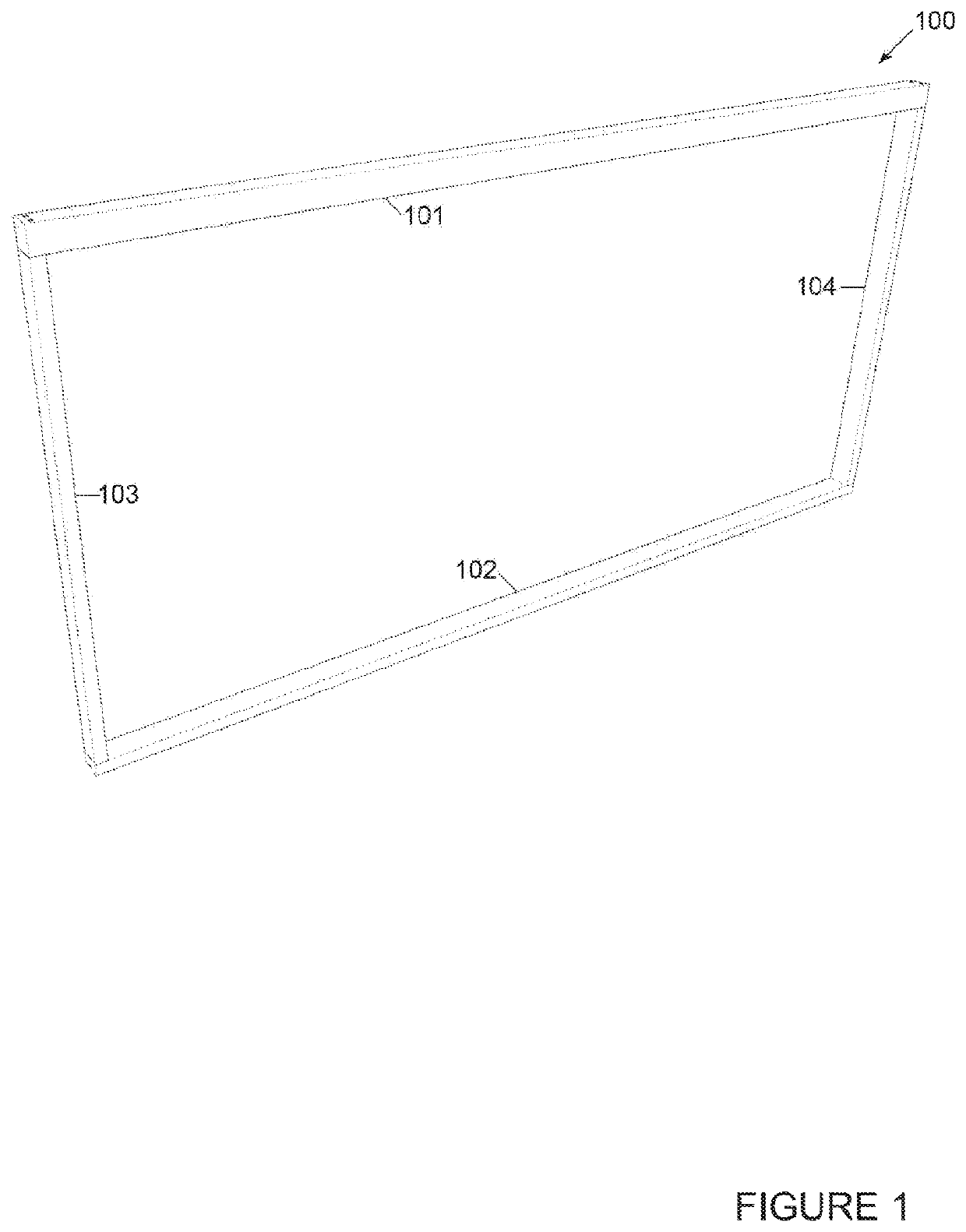
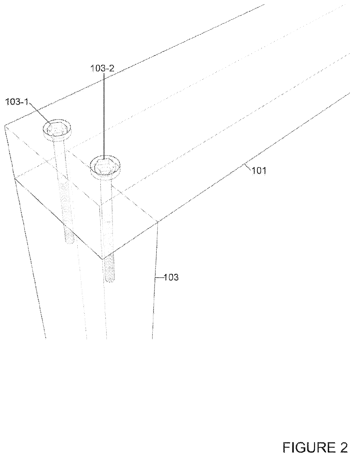
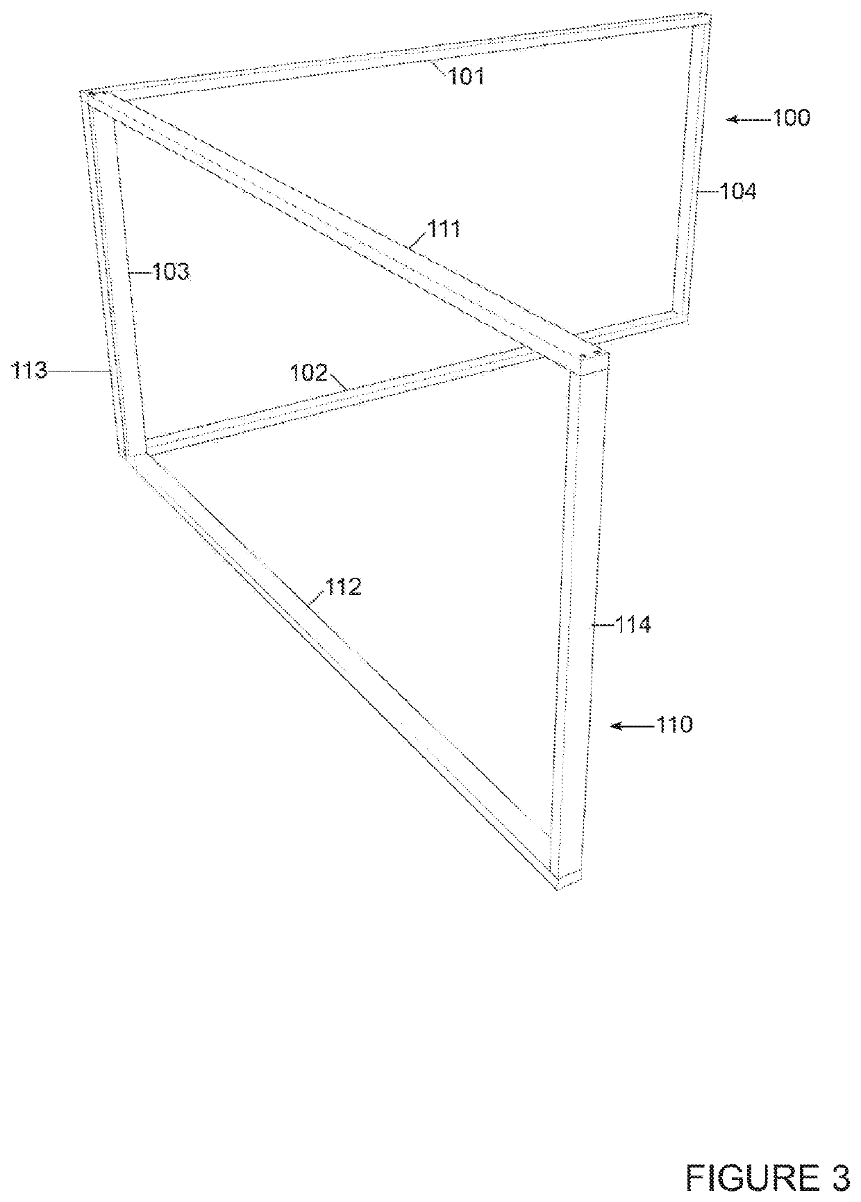
The present invention is about a new building construction method using heavy perimeter rails and braced frame slab assemblies with heavy perimeter rails. These assemblies are connected together using Slab to Slab Connectors, which transfer the load of the building to the foundation. The Slab To Slab Connectors secure the slabs together, ensuring that they can withstand high lateral shear loads. The pre-fabricated slabs can be easily moved and installed using cranes or other load lifting mechanisms. The invention allows for efficient and weather-independent construction, with significant cost savings and labor savings. The use of precision tools, preformed jigs, and hydraulic assemblies further reduces labor content and enables non-traditional structural concepts.

Problems solved by technology

There is a need for shear resistance in a wall, but large openings reduce the lateral (shear capacity) of the wall.
However, this solution is limited by the placement of windows and doors.
There are few architectural, structural or dimensional limitations with stick-built buildings like those imposed on modular and manufactured design by virtue of the roadway transportation limitations of manufactured structures.
While this method of construction has worked for many years, there are inherent inefficiencies in this method that result in significant cost penalties to the building buyer.
However, proper installation can be a problem using conventional methods.
The division of labor on job sites can result in improper connections.

Method used


Image

  • Building construction using braced frame slab assemblies having heavy perimeter rails
  • Building construction using braced frame slab assemblies having heavy perimeter rails
  • Building construction using braced frame slab assemblies having heavy perimeter rails

Examples


Embodiment Construction

[0045]The standard framing paradigm used in conventional construction is a “braced frame” structure where the bracing is provided via the OSB sheathing that covers the floors and walls once they are secured in place. Standard framing utilizes a uniform sheathing on both floors and walls (except at door and window openings) to create a braced frame (a.k.a. a diaphragm). The emphasis in this type of construction is the continuity of the OSB sheathing across the full extent of the wall and floor elements. For example, each of the parts in a wall frame is dedicated to a specific purpose—bottom plate, full studs, trimmer studs, headers, top plate, etc. There are no pieces in this structure that support another purpose—i.e. for the primary structural attachment of adjoining independent panelized components.

[0046]In contrast, the present Braced Frame Slab Assemblies Having Heavy Perimeter Rails incorporates heavy perimeter Rails for this purpose, which is a fundamental distinction over the...


PUM


Abstract

This invention relates to the construction of a building using Braced Frame Slab Assemblies Having Heavy Perimeter Rails that comprise Floor Slab and Wall Slab Assemblies formed of heavy perimeter Rails, with Rail Frame Connectors, such as a plurality of heavy threaded screws, joining the heavy perimeter Rails to form the Floor Slabs and Wall Slabs. The Slab can then be equipped with joists for floors or studs for walls, and with structural sheathing to provide shear load carrying capacity. The Slab to Slab Connectors also secure juxtaposed Floor Slabs and Wall Slabs.

Description

FIELD OF THE INVENTION[0001]This invention relates to the construction of a budding using Braced Frame Slab Assemblies Having Heavy Perimeter Rails that comprise Floor Slabs and Wall Slabs formed of heavy perimeter Rails, with Rail Frame Connectors joining the heavy perimeter Rails to form the Floor Slabs and Wall Slabs. Slab to Slab Connectors also secure juxtaposed Floor Slab and Wall Slabs. The structurally interconnected Slabs provide the required structural capacity for the building to resist high lateral shear loads. The prefabricated braced frame Floor Slabs and Wall Slabs can be placed into the building under construction using a crane or other load lifting mechanism.BACKGROUND OF THE INVENTIONThe Housing Industry Today[0002]In the prior art, the stick-built building is a product that is either custom built according to individual specifications, or as a builder's spec, or constructed as one of a plurality of pre-existing models in a housing development. These buildings are ...

Claims


Application Information

Patent Timeline
Patent Type & Authority Applications(United States)
IPC IPC(8): E04C3/16E04B1/10E04B2/70E04B5/02E04B5/12E04B1/08E04B2/58E04B5/10
CPCE04C3/16E04B1/10E04B2/706E04B5/023E04B2001/2652E04B1/08E04B2/58E04B5/10E04B5/12
Inventor COHEN, DAVID L
Owner VEGA BUILDING SYST LLC
Learn More