
Particle sensor and method

a particle sensor and particle technology, applied in particle and sedimentation analysis, measurement devices, instruments, etc., can solve the problems of low cost pm sensors that cannot provide size-resolved particle information for in-depth pollution pattern analysis, and cannot adjust the active size range dynamically, so as to achieve low cost

Inactive Publication Date: 2021-06-17
KONINKLJIJKE PHILIPS NV
View PDF0 Cites 1 Cited by
  • Summary
  • Abstract
  • Description
  • Claims
  • Application Information

AI Technical Summary

Benefits of technology

The patent describes a particle sensor that can detect particles based on their size range. The sensor has multiple modes of operation, including a coarse, fine, and ultrafine modes. Users can manually select the mode they need or the upper and lower size range for detection. This allows for more flexibility and adaptability in detecting particles. The sensor uses a unique laser intensity and pulse width for each mode, which increases its sensitivity and resolution. Overall, the particle sensor is low-cost and easy to use, with improved accuracy and flexibility.

Problems solved by technology

Unfortunately, almost no available low cost PM sensors can adjust the active size range dynamically, let alone provide a size-resolved particle distribution.
As low cost particle sensors usually have a large incident light spot and minimal control over particle flow, they cannot guarantee that each particle traverses the measurement zone individually, and hence the scattering signal captured will consist of a background contributed by fine particle ensembles and distinguishable peaks contributed by individual large particles.
However, these calibration parameters could potentially result in a deviation between the sensor reading and the true value if the actual particle size distribution varies from the calibration scenario.
In addition, the spectral-averaged number / mass concentration cannot either provide size-resolved particle information for in-depth pollution pattern analysis.
However, particle separators are usually bulky, and require professional operation and careful maintenance for accurate particle size separation.
In addition, such sensors require considerable extra hardware investment onto low cost particle sensors.

Method used


Image

  • Particle sensor and method
  • Particle sensor and method
  • Particle sensor and method

Examples


Embodiment Construction

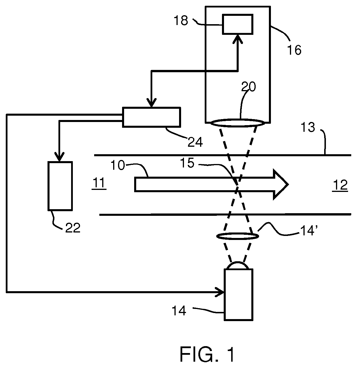
>[0064]This invention provides a particle sensor for sensing the number or mass concentration of particles within a particular particle size range in a sample of particles having a particular particle size distribution.

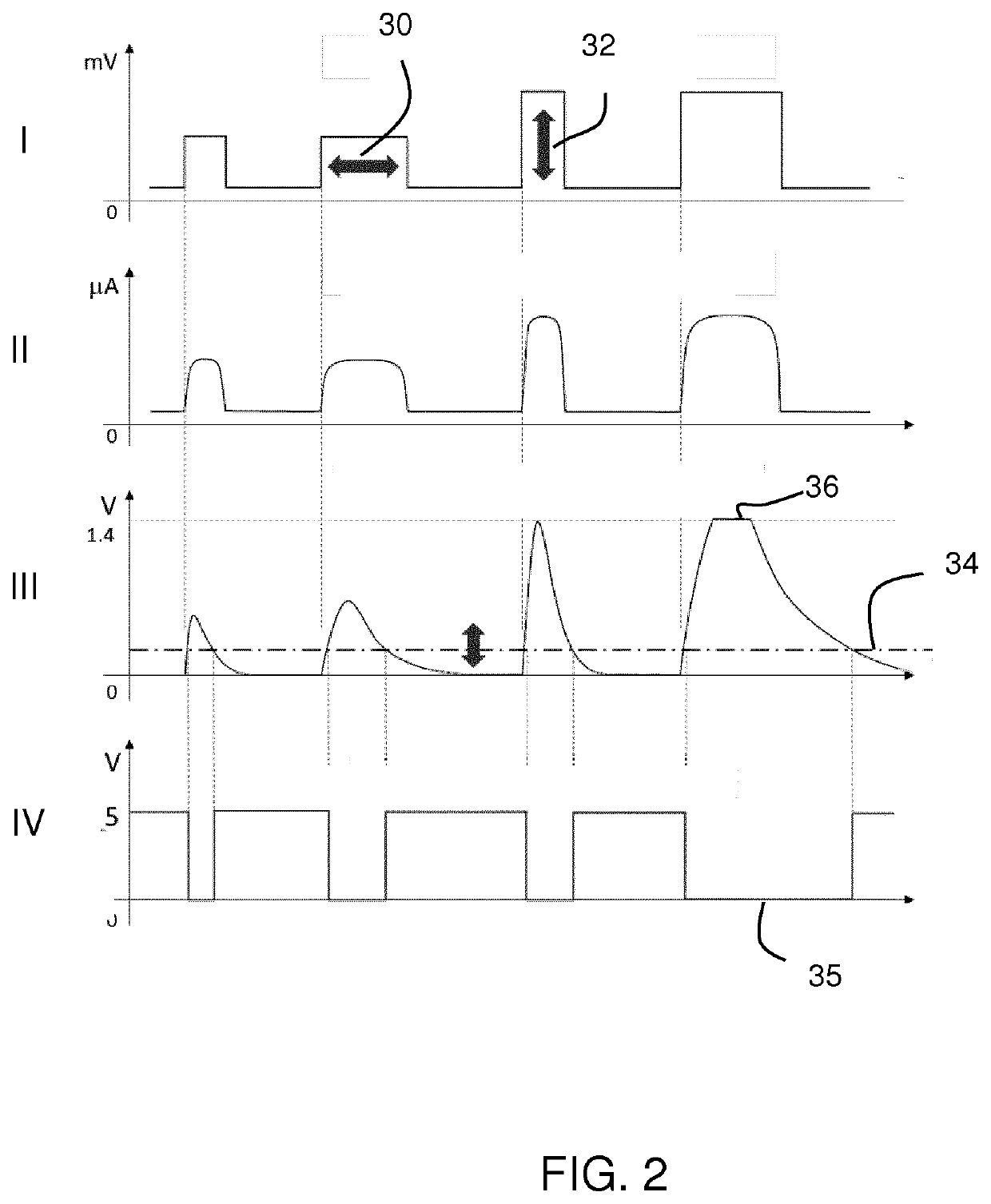
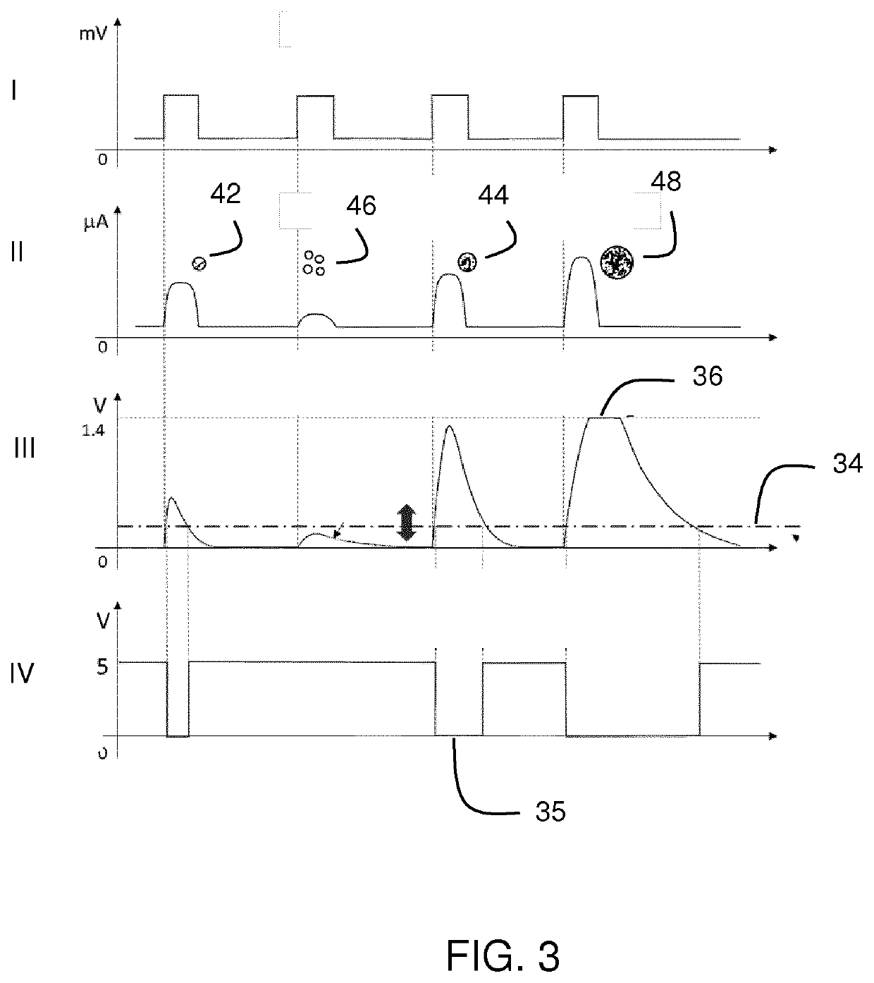
[0065]The particle sensor comprises a light source for providing light which is scattered by the particles to generate scattered light and a light detector for detecting the scattered light to provide a light detector signal. The particle sensor has a controller for analyzing the light detector signal to determine information relating to the particle size distribution and based on that information selecting a mode of operation of the particle sensor to sense the particles only within the particular size range.

[0066]Particle sensors which physically pre-separate particles in advance of sensing, thereby measuring only particles within a particular size range, are known. This invention is based on a particle sensor which has a controller to analyze the light detector sig...


PUM

PropertyMeasurementUnit
sizeaaaaaaaaaa
sizeaaaaaaaaaa
sizeaaaaaaaaaa

Abstract

A particle sensor is provided for sensing the number or mass concentration of particles within a particular particle size range, the particles having a particle size distribution. The sensor comprises a light source (14) for providing light which is scattered by the particles to generate scattered light; a light detector (16, 18) for detecting the scattered light to provide a light detector signal; and a controller (24) for analyzing the light detector signal to determine information relating to the particle size distribution. Based on that information relating to the particle size distribution, the controller selects a mode of operation of the particle sensor to sense the particles only within the particular size range.

Description

FIELD OF THE INVENTION[0001]This invention relates to a method and apparatus for characterizing particles.BACKGROUND OF THE INVENTION[0002]Low cost particle sensors are widely used in home appliances and integrated sensor boxes for particulate matter (PM) related air quality measurement. The sensor captures the intensity of scattered light by airborne particles and converts a sensor photocurrent to particle number and / or mass concentration according to the factory calibration parameters.[0003]Most low cost particle sensors are only able to report particle number and / or mass concentration over the entire factory set size range (e.g. <10 μm for PM10). However, in some circumstances, it is of more importance to further understand size-resolved particle number / mass distribution within the whole size range (e.g. subranges 2.5-5 μm and 5-10 μm within the whole range of PM10), especially for pollution pattern recognition and pollution sources determination. Unfortunately, almost no avai...

Claims


Application Information

Patent Timeline
Patent Type & Authority Applications(United States)
IPC IPC(8): G01N15/02
CPCG01N15/0211G01N2015/0046G01N15/1459G01N2015/0238G01N2015/1486G01N2015/1493
Inventor ZHANG, QIUSHICHEN, SHUANGSUIJVER, JAN FREDERIK
Owner KONINKLJIJKE PHILIPS NV
Learn More