Rotary cutting tool with hybrid cutting insert design

a cutting tool and hybrid technology, applied in the direction of metal-working equipment, milling machines, milling equipment, etc., can solve the problems of large deflection of milling cutters with long lengths, ineffective removal of swarf (i.e., chips) from cut, and thinner inserts with radial mounting are not as effective at removing chips from cut, etc., to achieve effective chip evacuation, reduce deflection, and adequate chip gash

Active Publication Date: 2021-06-03
KENNAMETAL INC
View PDF34 Cites 0 Cited by
  • Summary
  • Abstract
  • Description
  • Claims
  • Application Information

AI Technical Summary

Benefits of technology

[0005]By using two types of inserts having different thickness, the hybrid design of the invention provides adequate chip gash (i.e., flute) volume for effective chip evacuation where it is most critical toward the front of the milling cutter, and a larger cross-sectional core diameter where bending is the highest toward the base of the milling cutter. A finite element analysis (FEA) showed about a 30% decrease in deflection, as compared to a milling cutter with only radial mounted cutting inserts.
[0006]In one aspect of the invention, a rotary cutting tool comprises a cutting head having a plurality of insert-receiving pockets in a first cutting region proximate an end face of the rotary cutting tool and a second cutting region proximate a shank of the rotary cutting tool. A plurality of a first type of cutting inserts are mounted in the insert-receiving pockets of the first cutting region of the cutting head. Each first type of cutting insert has a first thickness. A plurality of a second type of cutting inserts are mounted in the insert-receiving pockets of the second cutting region of the cutting head. The plurality of the first type of cutting inserts provide an increased chip gash volume for effective chip evacuation, and the plurality of the second type of cutting inserts provide an increased core diameter to minimize deflection of the rotary cutting tool.

Problems solved by technology

Milling cutters with long lengths experience large deflection when cutting loads are applied.
This causes excess stresses at the base of the cutter that have been seen to exceed the yield strength of the cutter body material, causing failure.
However, the thinner inserts are not as efficient at removing swarf (i.e., chips) from the cut as radially mounted inserts because the chip gash (i.e., flute) is also thinner.

Method used


Image

  • Rotary cutting tool with hybrid cutting insert design
  • Rotary cutting tool with hybrid cutting insert design
  • Rotary cutting tool with hybrid cutting insert design

Examples


Embodiment Construction

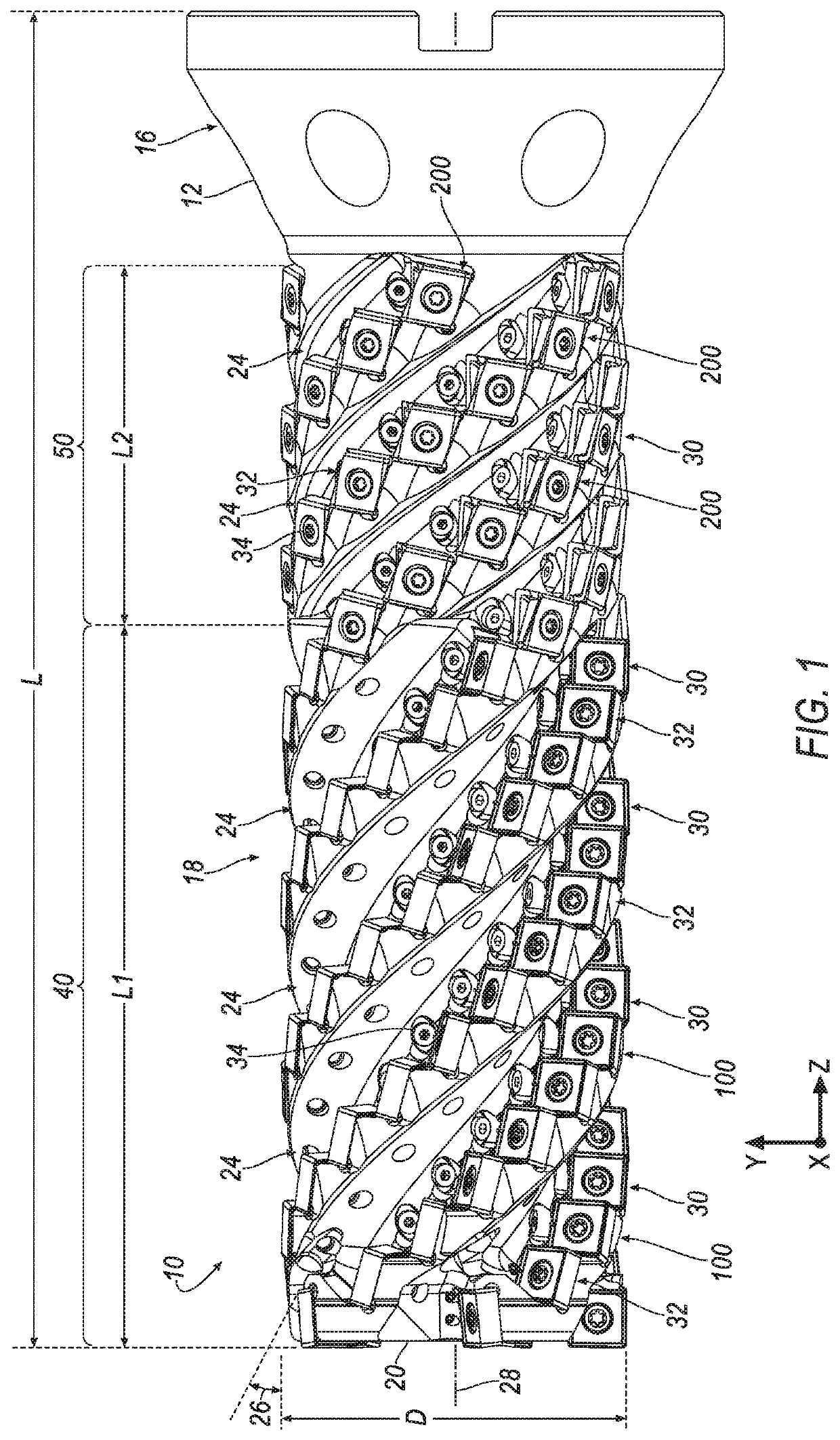
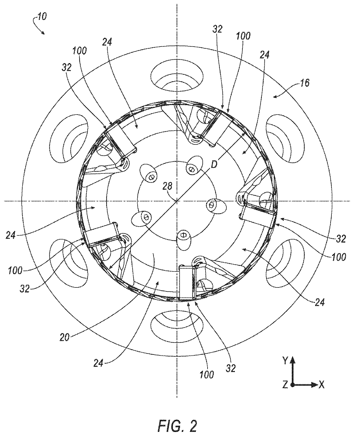
[0023]Referring now to FIGS. 1 and 2, a rotary cutting tool is shown generally at 10 according to an embodiment of the invention. In general, the rotary cutting tool 10 comprises a helical milling cutter including a cutter body 12 having an elongated and generally cylindrical shape. The cutter body 12 comprises a shank 16 and a cutting head 18. The shank 16 is configured so as to be capable of insertion and securing within the spindle of a milling machine (not shown) as is well known in the art. In the illustrated embodiment, the shank 16 has a tapered design so as to be capable of this insertion and securing within the spindle. However, it should be appreciated that the shank 16 may be of any shape or design so as to be capable of inserting and securing within the spindle. Such designs include, but are not limited to, V-flange, shell mill mount, Weldon shank, and the like. In the illustrated embodiment, the rotary cutting tool has a large length to diameter ratio (i.e., L / D ratio) ...


PUM


Abstract

A rotary cutting tool includes a cutting head having a plurality of insert-receiving pockets for radially mounting a first type of cutting insert in a first cutting region and for tangentially mounting a second type of cutting insert in a second cutting region. The first cutting region has a first length, L1, and the second cutting region has a second length, L2, that is greater in magnitude than the first length, L1. The two types of cutting inserts provides a hybrid cutting insert design in which the first type of cutting inserts provide an increased chip gash volume for effective chip evacuation, and the second type of cutting inserts provide an increased core diameter to minimize deflection of the rotary cutting tool.

Description

BACKGROUND OF THE INVENTIONField of the Invention[0001]The invention relates to rotary cutting tools with cutting inserts mounted thereon, and in particular to a helical milling cutter with a hybrid design having at least one leading row of a first type of radially mounted cutting inserts and at least one trailing row of a second type of tangentially mounted cutting inserts.Description of Related Art[0002]Milling cutters with long lengths experience large deflection when cutting loads are applied. This causes excess stresses at the base of the cutter that have been seen to exceed the yield strength of the cutter body material, causing failure.[0003]Tangentially mounted inserts improve this situation because they are thinner in the radial direction and allow for a bigger core diameter on the cutter body. However, the thinner inserts are not as efficient at removing swarf (i.e., chips) from the cut as radially mounted inserts because the chip gash (i.e., flute) is also thinner. To be ...

Claims


Application Information

Patent Timeline
Patent Type & Authority Applications(United States)
IPC IPC(8): B23C1/02
CPCB23C1/02B23C2210/16B23C5/02B23C5/20B23C5/22B23C2200/286B23C5/109B23C5/202B23C2200/0455B23C2200/0494B23C2200/367
Inventor BRUNETTO, LANCE DAVIDFILHO, RUY FROTA DE SOUZADUDZINSKY, RONALD LOUIS
Owner KENNAMETAL INC
Why Eureka
Try Eureka