Drug injection device with deflectable transducers

a technology of deflectable transducers and injection devices, which is applied in the direction of intravenous devices, other medical devices, infusion syringes, etc., can solve the problems of inability to achieve the effect of reducing the number of errors of the switch structure, limiting the use of electronic features like the ones above, and generally prone to errors. , to achieve the effect of reducing or eliminating at least one drawback

Active Publication Date: 2021-06-03
NOVO NORDISK AS
View PDF0 Cites 1 Cited by
  • Summary
  • Abstract
  • Description
  • Claims
  • Application Information

AI Technical Summary

Benefits of technology

The invention provides a drug injection device with reliable detection of changes in its state, electronic determination of the set and expelled dose of drug, and relatively simple and inexpensive manufacturing. The device has a ratchet mechanism to prevent relative movement between elements and can be used with a spring-drive or manual expelling mechanism. The device can be used for both short-term and continuous drug delivery.

Problems solved by technology

Until recently, the use of electronic features like the ones above has been limited to durable injection devices, as the additional cost connected with an inclusion of such features in a disposable injection device has been considered to lead to an economically unviable end product.
Switch structures are generally prone to errors, for example faulty switch activations, during handling or transportation.
In particular, in case of the device being unintentionally dropped on a hard surface, an impact may cause erroneous switch activation.

Method used


Image

  • Drug injection device with deflectable transducers
  • Drug injection device with deflectable transducers
  • Drug injection device with deflectable transducers

Examples


Embodiment Construction

[0069]When in the following relative expressions, such as “clockwise” and “counter-clockwise”, “left” and “right”, etc. are used, these refer to the appended figures and not necessarily to an actual situation of use. The shown figures are schematic representations for which reason the configuration of the different structures as well as their relative dimensions are intended to serve illustrative purposes only.

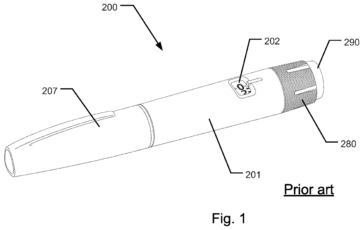
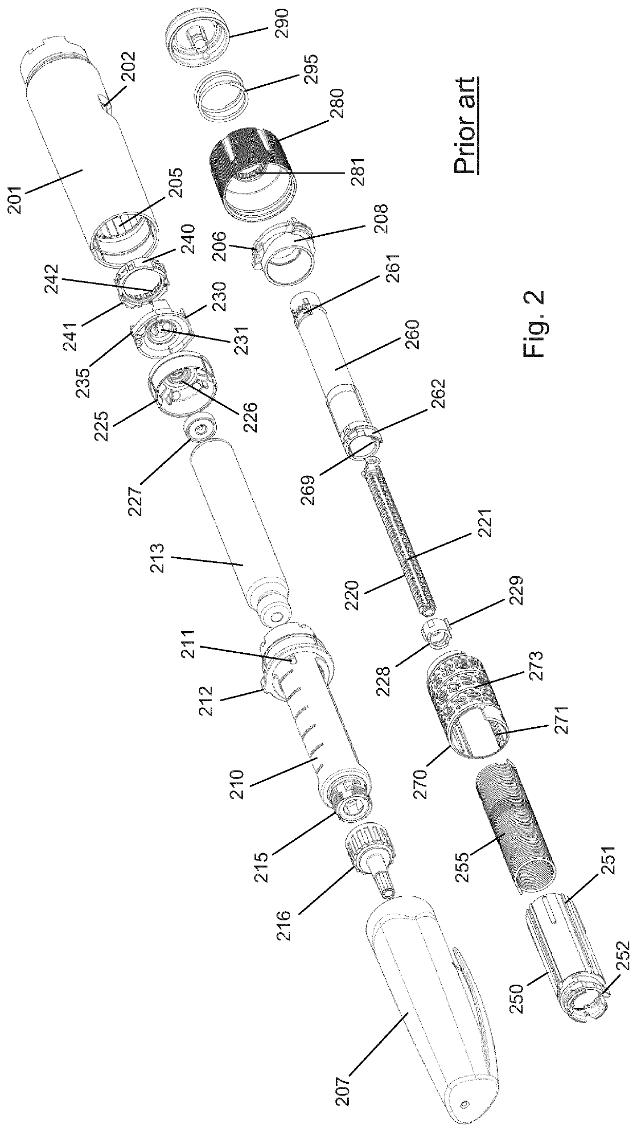
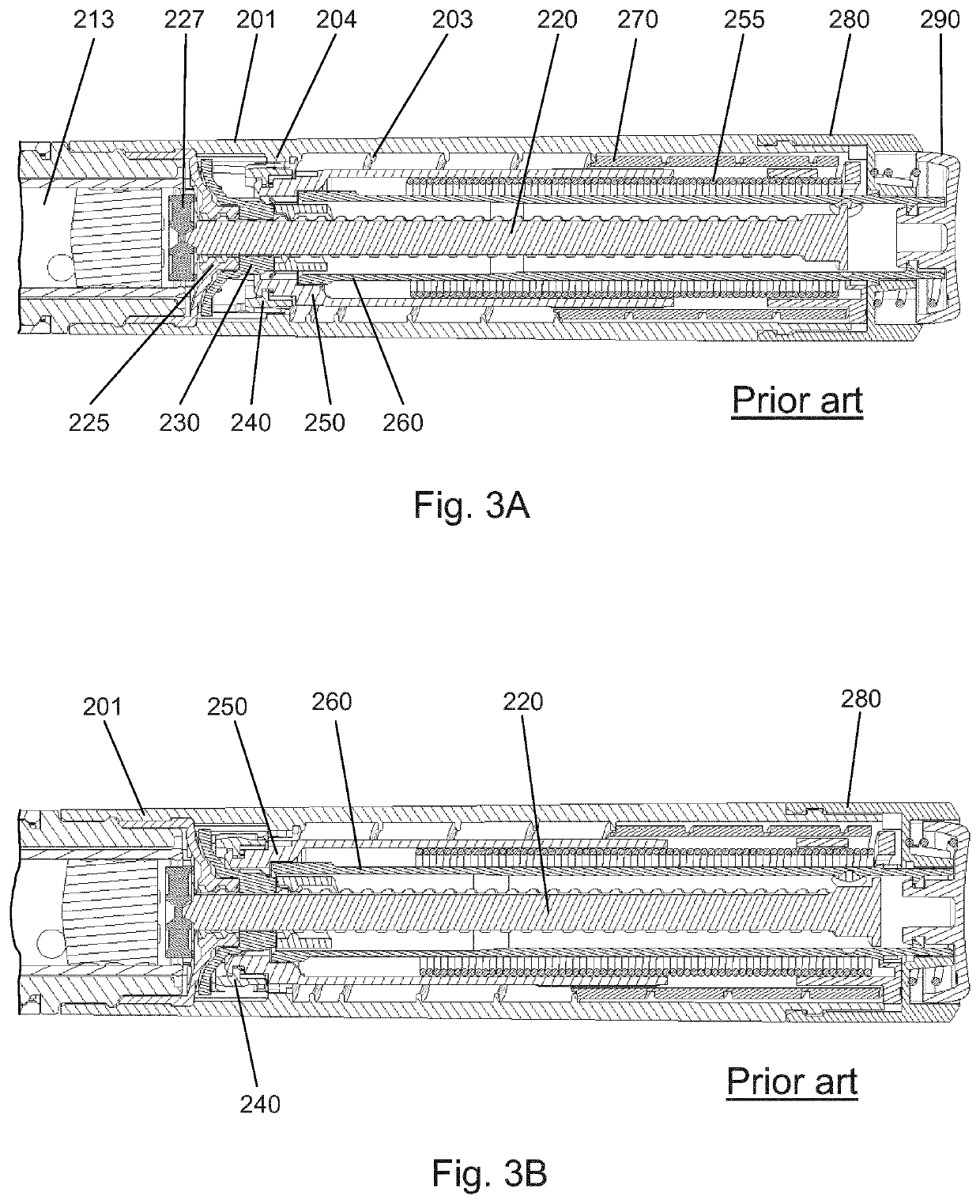
[0070]FIG. 1 shows a prior art drug delivery device in the form of a pen-formed auto-injection device 200, i.e. a so-called “injection pen” that includes an expelling mechanism incorporating a spring drive. FIG. 2 shows an exploded view of the prior art auto-injection device 200 shown in FIG. 1. FIGS. 3A and 3B show cross sectional views of the expelling mechanism of the prior art auto-injection device 200 shown in FIGS. 1 and 2 where FIG. 3A shows the device in dose setting state and FIG. 3B shows the device in dose expelling state.

[0071]In the present context the device 200 ...


PUM


Abstract

The present invention provides a drug injection device (100) comprising a first element (140) and a second element (103) configured to undergo unidirectional movement relative to each other corresponding to an action performed on or by the drug injection device (100), wherein the first element (140) comprises a plurality of serially disposed protrusions (143), wherein the second element (103) comprises first and second deflectable transducers (103a / 153a, 103b / 153b) configured for sequentially cooperating with the plurality of protrusions (143), and wherein a processor (151) is electrically connected with the first and second deflectable transducers (103a / 153a, 103b / 153b) to register activation signals, wherein the protrusion configuration is so disposed on the first element (140) and the first and second deflectable transducers (103a / 153a, 103b / 153b) are so disposed on the second element (103) that a second activation signal generated by the second deflectable transducer (103b / 153b) is delayed relative to a first activation signal generated by the first deflectable transducer (103a / 153a) as the first element (140) and the second element (103) move relative to each other, and wherein the processor (151) is configured to provide a) a first control action if a time delay between the first and second activation signals is above or equal to a pre-defined value, and b) a second control action if said time delay is below said pre-defined value.

Description

FIELD OF THE INVENTION[0001]The present invention relates generally to devices for delivering medicine to a subject, and more specifically to injection devices capable of expelling one or more doses of drug from a drug reservoir.BACKGROUND OF THE INVENTION[0002]In the diabetes care segment parenteral drug administration carried out using a traditional vial and syringe system is increasingly being substituted by administration using a pen injection device. Pen injection devices are particularly convenient in that they allow the user to perform a dosed injection from a prefilled drug reservoir without first having to manually transfer the particular dose from one reservoir (the vial) to another (the syringe).[0003]Predominantly, two types of pen injection devices are available, durable injection devices being capable of delivering one or more doses of drug from a prefilled drug cartridge which can be loaded into the device before use and replaced after exhaustion, and disposable injec...

Claims


Application Information

Patent Timeline
IPC IPC(8): A61M5/315
CPCA61M5/31593A61M2005/3126A61M5/31583A61M5/24A61M5/31565A61M5/31566A61M2205/0294A61M2205/50A61M2205/581A61M5/3155A61M5/31585A61M2205/3569A61M2205/3553A61M2005/3125A61M2205/3327
Inventor GRUBBE, MIKKEL SCHOUENBORG
Owner NOVO NORDISK AS
Why Eureka
Try Eureka