
Bearing with at least one sealing element and at least one adjusting shim for axially displacing said sealing element

Active Publication Date: 2021-05-13
AB SKF
View PDF0 Cites 1 Cited by
  • Summary
  • Abstract
  • Description
  • Claims
  • Application Information

AI Technical Summary

Benefits of technology

The present invention is about a new kind of bearing that has special sealing elements to keep out foreign objects and increase the lifespan in challenging environments. It also has an adjusting shim that allows the sealing elements to have different running surfaces,which increases their service life by displacing the shim along the sealing running surface. A collar keeps the sealing elements in place and performs their sealing duties. Additionally, using a segmented shim makes it easier to mount and reduces costs. Overall, this new design provides better protection and improved durability for bearings in high-temperature and high-load environments.

Problems solved by technology

Those external elements may also alter the sealing element itself, leading to a reduction in the sealing element service life.
However, the sealing of such bearings may be insufficient, notably for use in a submersible machine or in a tunnel boring machine.
Indeed, the first sealing element is the first seal to be damaged.
Adding sealing elements increases the cost of the rolling bearing, as well as its weight.
Furthermore, after several years of use, the sealing elements running surface wears.
The ring including such running surface must then be changed, which increases the maintenance costs of the rolling bearing.
Indeed, the rings of rolling bearings used in slewing bearings or bearings for tunnellers are quite expensive, due to the material used for those rings that has to be corrosion resistant as well as hard to limit wear.

Method used


Image

  • Bearing with at least one sealing element and at least one adjusting shim for axially displacing said sealing element
  • Bearing with at least one sealing element and at least one adjusting shim for axially displacing said sealing element
  • Bearing with at least one sealing element and at least one adjusting shim for axially displacing said sealing element

Examples


Embodiment Construction

[0056]The expressions “outer” and “inner” refer to the rotation axis X1-X1 of the bearing, the inner parts being closer to the rotation axis than the outer parts.

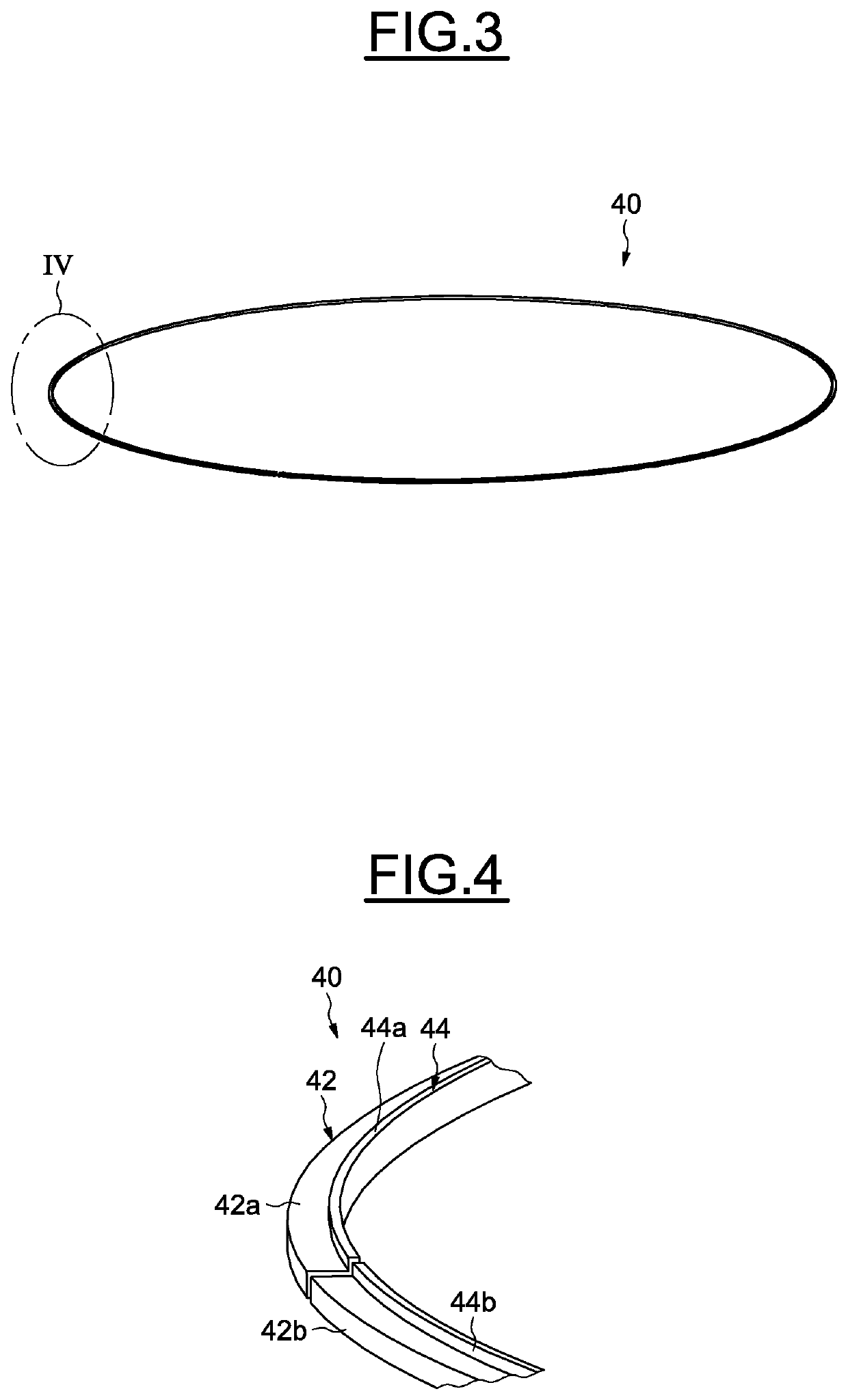
[0057]Referring first to FIGS. 1 to 4, which illustrate an embodiment of a bearing 10, for example a slewing bearing of large diameter intended to be used in particular in marine applications, such as, for example, a tidal power station (not shown).

[0058]The slewing bearing 10 comprises an outer ring 12 as a first ring, a rotating inner ring 14 as a second ring, two rows of rolling elements 16, 17, such as for example balls, arranged between the inner and outer rings 12, 14, and two cages 18, 19 each configured to maintain the circumferential spacing of the rolling elements of each row 16, 17. Such slewing bearing 10 forms an axial thrust configured to transmit axial and radial loads, as well as torques.

[0059]As an alternative, it is possible to conceive a single row of rolling elements between the inner and outer rings to ...


PUM


Abstract

A bearing providing a first ring assembly and a second ring assembly, the first ring assembly including at least a first ring and an outer cap reversibly fixed to first ring. The bearing further providing at least one sealing element mounted radially into a cylindrical surface of the first ring assembly and provided with a sealing lip in sliding frictional contact with the second ring assembly. The bearing including at least one adjusting shim mounted radially between the first and second ring assemblies, the adjusting shim being axially located between the outer cap of the first ring assembly and the sealing element; or between the first ring of the first ring assembly and the sealing element.

Description

CROSS-REFERENCE TO RELATED APPLICATIONS[0001]This application claims priority to German Patent Application no. 102019217411.6, filed Nov. 12, 2019, the contents of which is fully incorporated herein by reference.TECHNICAL FIELD OF THE INVENTION[0002]The present invention relates to the field of rolling bearings. More particularly, the invention concerns the field of sealings mounted between two rings of a rolling bearings.BACKGROUND OF THE INVENTION[0003]The invention relates to large diameter rolling bearings, notably slewing bearings used in marine applications, for example in a tidal or marine turbine power station.[0004]The invention is not limited to such application, and can be used in other application, such as large diameter rolling bearings used in tunnel boring machines, such as tunnellers.[0005]Large diameter rolling bearings generally comprise an inner ring, an outer ring and sealing elements disposed between the rings in order to define a closed annular space within whi...

Claims


Application Information

Patent Timeline
IPC IPC(8): F16C33/76F16C19/18
CPCF16C33/76F16C19/18F16C33/7806F16C33/7823F16C33/7826F16C33/783F16C33/7896F16C19/181F16C19/381F16C33/768F16C2300/14F16C2300/42F16C2360/00F16C33/7886F16C33/586
Inventor CAPOLDI, BRUNODELABY, JULIETTEDONDAINE, HERVE
Owner AB SKF
Learn More