Winding arrangement for use in magnetic devices

a winding arrangement and magnetic device technology, applied in the direction of coils, basic electric elements, electrical apparatus, etc., can solve the problems of physical limitations of the size and geometry of the conductor, the difficulty of handling high frequency currents in a compact structure, and the inability to avoid one current carrying conductor being immersed in the magnetic field of neighboring current carrying conductors, etc., to achieve the effect of reducing the proximity effect, and reducing the high frequency loss

Pending Publication Date: 2021-04-22
MURATA MFG CO LTD
View PDF0 Cites 0 Cited by
  • Summary
  • Abstract
  • Description
  • Claims
  • Application Information

AI Technical Summary

Benefits of technology

The proposed coils and winding arrangement in this patent allow for the placement of conductors carrying current in opposite directions close to each other, which reduces high frequency losses and lowers manufacturing limitations. This arrangement also allows for the construction of high power transformers operating at much higher frequencies and improves heat flow between windings. Overall, this patent makes it possible to achieve high power levels at high frequencies and eliminates manufacturing difficulties of previous constructions.

Problems solved by technology

One of the major difficulties in constructing single module high frequency power magnetics is the difficulty associated with handling high frequency currents in a compact structure.
This makes it impossible to avoid one current carrying conductor getting immersed in the magnetic field of neighboring current carrying conductors.
At high frequencies and high currents, there are physical limitations to the size and geometry of conductors.
This imposes machining challenges when manufacturing windings of conductors with such unusual aspect ratios.
This has a number of machining difficulties and limits the power that can be achieved in a single unit.
This also obstructs the flow of heat making it difficult to achieve high power densities.

Method used


Image

  • Winding arrangement for use in magnetic devices
  • Winding arrangement for use in magnetic devices
  • Winding arrangement for use in magnetic devices

Examples


Embodiment Construction

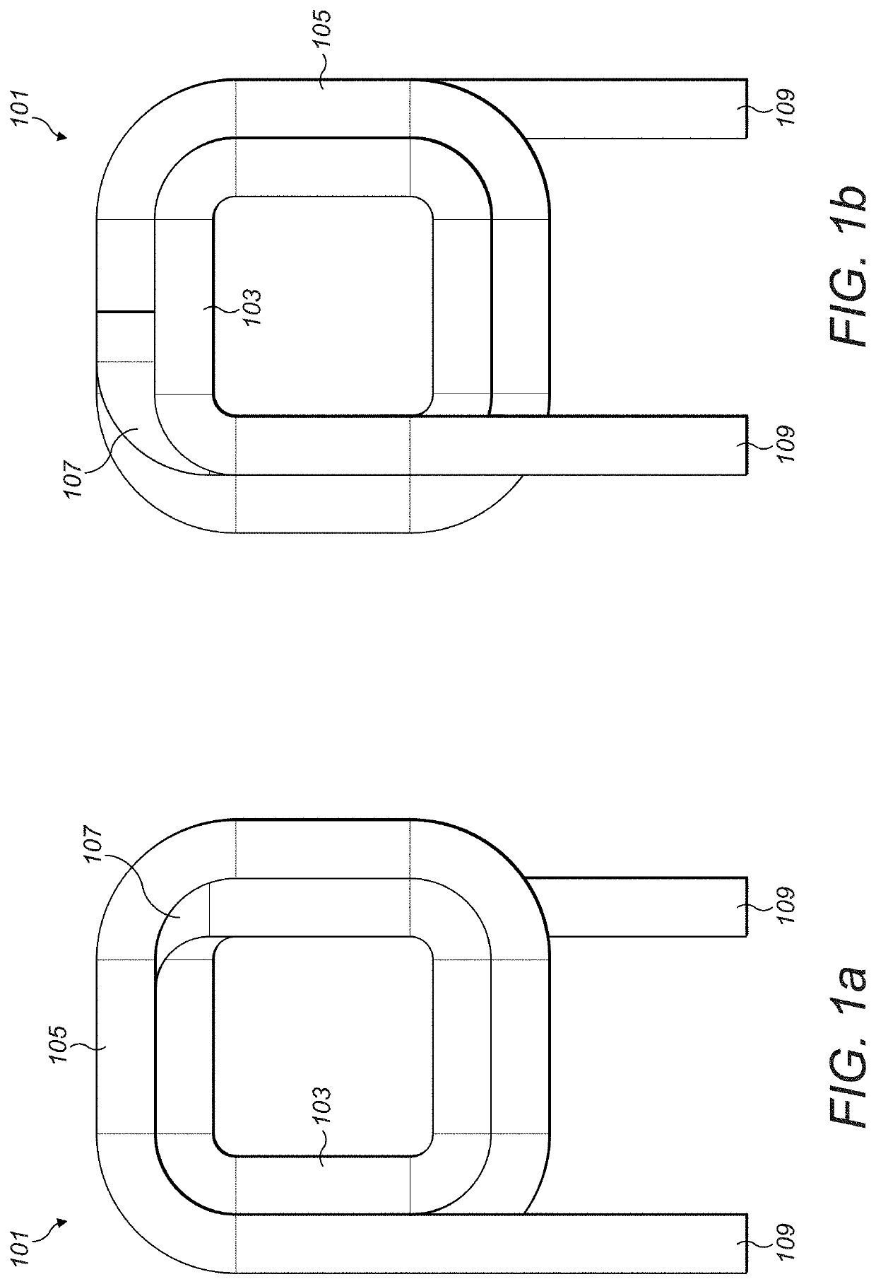
[0032]FIGS. 1a and 1b show an example of a coil 101 according to a preferred embodiment of the present invention. In FIG. 1a, a plan view of the coil 101 from one side is shown, and in FIG. 1b, a plan view of the coil 101 from the opposite side is shown. That is, the views are looking from opposite ends of the coil along its winding axis, which runs longitudinally through all of the turns of the coil.

[0033]In FIGS. 1a and 1b, an electrically conductive material is configured into the shape of a coil 101. The coil includes two main sections: a first section including a first plurality of turns 103 and a second section including a second plurality of turns 105. These two sections are integral to each other, in this case being joined by a cross-over portion 107, and the coil 101 terminates at either end by connection portions 109.

[0034]The first 103 and second plurality of turns 105 are each arranged around the winding axis of the coil. In the example coil 101 of FIGS. 1a and 1b, the f...


PUM


Abstract

A coil of electrically conductive material includes first and second sections, the first section including a first plurality of turns and the second section including a second plurality of turns. Both the first plurality of turns and the second plurality of turns are arranged around a winding axis of the coil. The first plurality of turns are smaller than the second plurality of turns such that when viewed along the winding axis of the coil, the first plurality of turns fit within the second plurality of turns. When viewed perpendicular to the winding axis of the coil, the first and second sections are adjacent.

Description

CROSS REFERENCE TO RELATED APPLICATIONS[0001]This application claims the benefit of priority to United Kingdom Patent Application No. 1809486.2 filed on Jun. 8, 2018 and is a Continuation Application of PCT Application No. PCT / GB2019 / 051602 filed on Jun. 7, 2019. The entire contents of each application are hereby incorporated herein by reference.BACKGROUND OF THE INVENTION1. Field of the Invention[0002]This application relates to a winding arrangement for use in magnetic devices, in particular, a coil of electrically conductive material for use in a magnetic device.2. Description of the Related Art[0003]One of the major difficulties in constructing single module high frequency power magnetics is the difficulty associated with handling high frequency currents in a compact structure. The nature of the magnetic component construction requires the conductors carrying the electrical currents to be placed in close proximity to each other. This makes it impossible to avoid one current carr...

Claims


Application Information

Patent Timeline
IPC IPC(8): H01F27/28H01F27/24
CPCH01F27/2823H01F27/24H01F27/2847H01F30/10H01F41/061H01F41/071H01F27/34H01F27/006H01F5/00H01F27/28
Inventor WARNAKULASURIYA, KAPILA
Owner MURATA MFG CO LTD
Why Eureka
Try Eureka