3D printing of additive-free mxene ink for fabrication of micro-supercapacitors with ultra-high energy densities
a micro-supercapacitor and additive-free technology, applied in the direction of additive manufacturing processes, cell components, additive manufacturing with solid and fluid, etc., can solve the problems of scalable fabrication of 3d devices that utilize high-performance electrode materials, affecting the electrical and electrochemical properties of printed electrodes, and unable to meet the requirements of micro-supercapacitors, etc., to achieve high energy densities, high power devices, and suitable for integration with miniaturized electronics
- Summary
- Abstract
- Description
- Claims
- Application Information
AI Technical Summary
Benefits of technology
Problems solved by technology
Method used
Image
Examples
example 1
MAX Phases Synthesis
[0101]The synthesis of Ti3AlC2 MAX phase was performed in 2 steps. First, Ti2AlC MAX phase was synthesized by mixing TiC powder (99.5% Alfa Aesar), Ti powder (99.5%, Alfa Aesar), and Al powder (99.5%, 325 mesh, Alfa Aesar) in a 1:1:1 molar ratio. The mixture was ball milled for 24 hours, then sintered at 1400° C. for 2 h under flowing Argon with a 5° C. / min heating rate. The resulting material was milled into a fine powder, sieved, and Ti2AlC powder with a particle size of less than 38 μm was used in the next step. For the synthesis of Ti3AlC2, the resulting Ti2AlC powder was mixed with TiC powder (99.5% Alfa Aesar) in a 1:1 molar ratio, ball milled for 24 h and then sintered at 1400° C. for 2 h under flowing Argon with a 10° C. / min heating rate. The resulting sintered material was milled, sieved, and particles of less than 38 μm were used for MXene ink preparation.
MXene Synthesis
[0102]The Ti3C2Tx suspension was prepared as follows. Briefly, concentrated hydrochl...
example 2
Atomic Force Microscope (AFM)
[0105]AFM (Park Systems, NX10) was used to measure the size and thickness of the synthesized Ti3C2Tx flakes. To prepare the AFM samples, a small amount of the solution was diluted with DI water and drop-casted on the pieces of thermally oxidized silicon wafers.
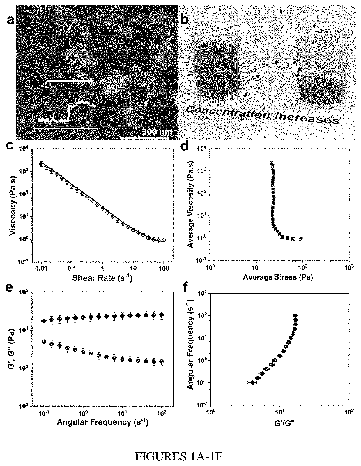
[0106]Atomic force microscopy (AFM) measurements showed that the synthesized MXenes are mostly single-layer flakes with an average lateral dimension of ˜0.3 μm (FIG. 1A). However, the concentration of the prepared dispersions (˜10 mg mL−1) may be too low to achieve the rheological properties required for extrusion printing and, thus, increasing the concentration of MXene dispersions was undertaken.
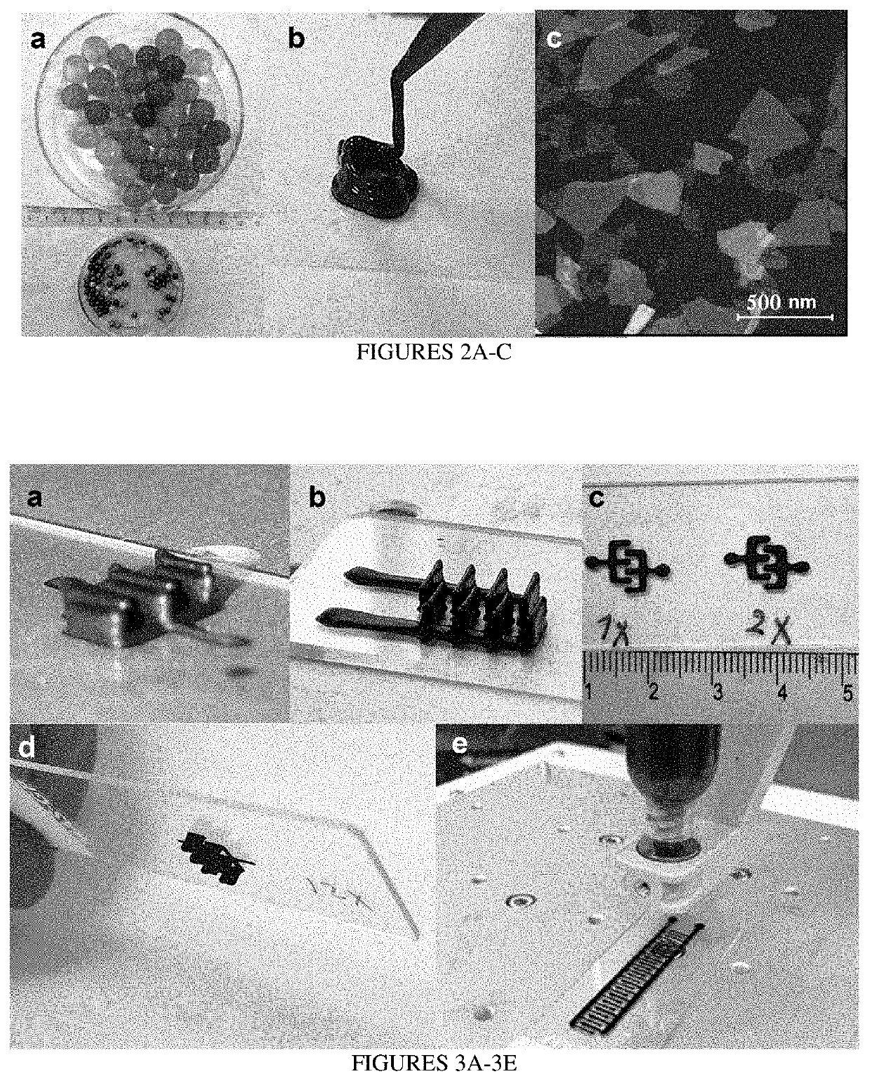
[0107]The instant example uses superabsorbent polymer (SAP) for concentrating Ti3C2Tx dispersions (FIGS. 2A-2C). As schematically demonstrated in FIG. 1B, the dispersion concentration was uniformly increased to as high as 290 mg mL−1 (˜28.9 wt %), thus preparing highly concentrated MXene dispersions. The ...
example 3
3D Printing
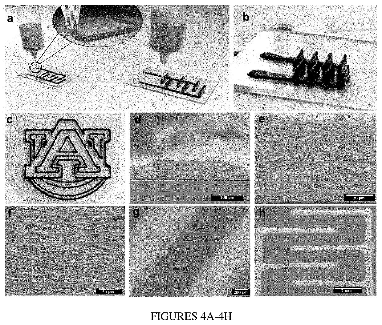
[0111]The first step in 3D printing of MSCs was the preparation of a printable MXene ink as described above. A benchtop robotic dispenser (Fisnar F4200n) was used for the 3D printing of MXene ink. The desired pattern was designed (AutoCAD, Autodesk Inc), transferred to the robotic dispenser, and printed using control software. The ink flow was controlled by a pneumatic fluid dispenser (DSP501N, Fisnar), the pressure of the dispenser and the printhead speed were ˜4 psi and ˜3 mm s−1, respectively. For printing interdigital electrodes with various height, after printing the first layer (current collector), the ink was deposited layer by layer on the finger part of the interdigital electrodes to increase the height of the electrodes.
Fabrication of MSCs
[0112]A glass substrate (MAS-GP, Matsunami Glass, IND., LTD., Japan) was cleaned with DI water and used for printing. Although the ink has high conductivity and could be used as both current collector and active material, that ...
PUM
| Property | Measurement | Unit |
|---|---|---|
| wt % | aaaaa | aaaaa |
| wt % | aaaaa | aaaaa |
| wt % | aaaaa | aaaaa |
Abstract
Description
Claims
Application Information
 - R&D
- Intellectual Property
- Life Sciences
- Materials
- Tech Scout
- Unparalleled Data Quality
- Higher Quality Content
- 60% Fewer Hallucinations
Browse by: Latest US Patents, China's latest patents, Technical Efficacy Thesaurus, Application Domain, Technology Topic, Popular Technical Reports.
© 2025 PatSnap. All rights reserved.Legal|Privacy policy|Modern Slavery Act Transparency Statement|Sitemap|About US| Contact US: help@patsnap.com


