Metal-carbon fiber reinforced plastic material composite and method of producing metal-carbon fiber reinforced plastic material composite

a technology of metal-carbon fiber reinforced plastics and composites, which is applied in the direction of transportation and packaging, coatings, chemical instruments and processes, etc., can solve the problems of increasing the cost of various members, cfrp is expensive generally, and is subjected to brittle fracture when deformed, and achieves excellent adhesion and adhesion durability

Pending Publication Date: 2021-04-22
NIPPON STEEL CORP
View PDF0 Cites 0 Cited by
  • Summary
  • Abstract
  • Description
  • Claims
  • Application Information

AI Technical Summary

Benefits of technology

The present invention provides a method of producing a metal-carbon fiber reinforced plastic material composite that has excellent adhesion and durability. This is achieved by forming primary bonds at the interface between the materials, which helps to suppress thermal strain and provides a more stable bond. The use of a room temperature curable modified silicone adhesive as a mastic adhesive further improves the adhesive durability through water.

Problems solved by technology

In the meantime, a matrix resin of the CFRP is generally a thermosetting resin such as an epoxy resin and has brittleness, and thus may be subjected to brittle fracture when deformed.
Further, the CFRP are expensive generally and are a factor in increasing the cost of various members such as automotive members.
Incidentally, a composite member made of a metal member and CFRP is a composite material composed of members with different properties, and thus, if the adhesion at the interface is not good, it is impossible to obtain the original performance of the composite material.
Among others, water and water vapor penetrate into the composite material, to thereby cause a defect of reduced adhesion in some cases.

Method used


Image

  • Metal-carbon fiber reinforced plastic material composite and method of producing metal-carbon fiber reinforced plastic material composite
  • Metal-carbon fiber reinforced plastic material composite and method of producing metal-carbon fiber reinforced plastic material composite
  • Metal-carbon fiber reinforced plastic material composite and method of producing metal-carbon fiber reinforced plastic material composite

Examples


first embodiment

[1.1. Configuration of a Metal-Carbon Fiber Reinforced Plastic Material Composite]

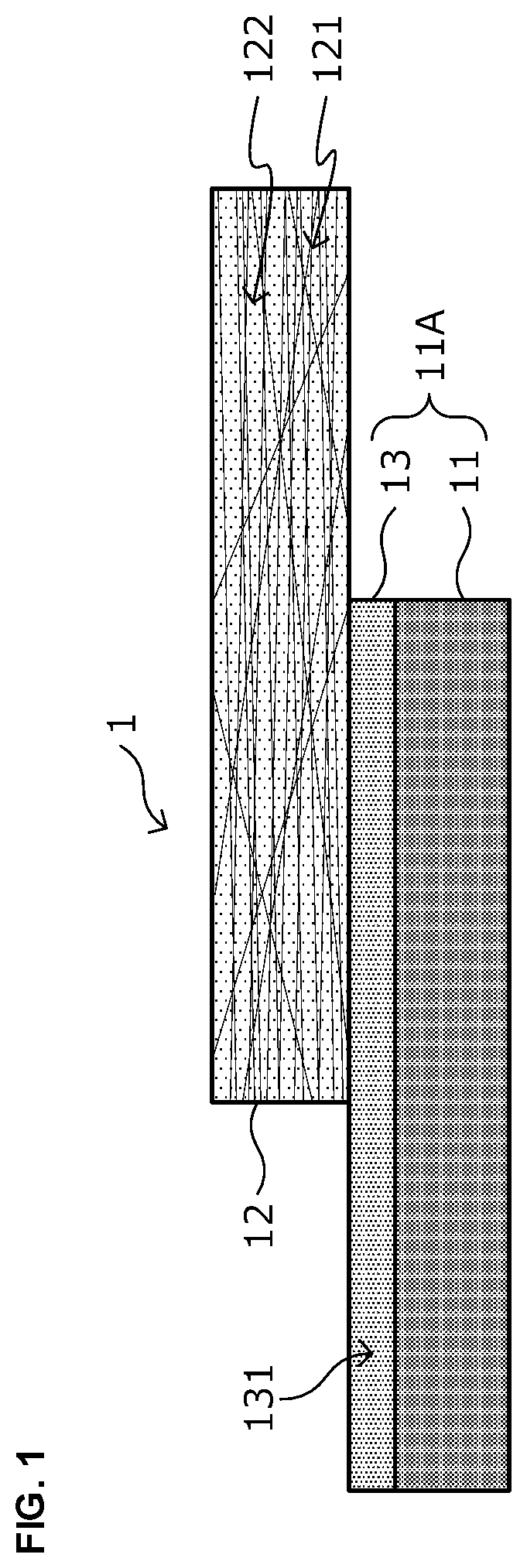
[0042]First, there will be explained a configuration of a metal-carbon fiber reinforced plastic material composite according to a first embodiment of the present invention with reference to FIG. 1. FIG. 1 is a schematic view illustrating a cross-sectional structure of a metal-carbon fiber reinforced plastic material composite 1 in a lamination direction as one example of the metal-carbon fiber reinforced plastic material composite according to this embodiment.

[0043]As illustrated in FIG. 1, the metal-carbon fiber reinforced plastic material composite 1 is a composite (composite member) in which a CFRP layer 12 as one example of a carbon fiber reinforced plastic material, is bonded to at least a portion of a metal plate 11 with a coating layer 13 formed beforehand on a surface thereof, or a metal member 11A obtained by processing the metal plate 11 by press-molding or the like, on which the coating laye...

second embodiment

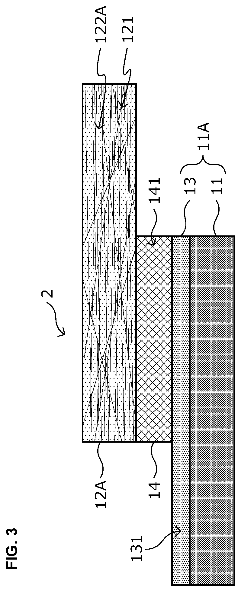
[0118]There will be briefly explained a metal-carbon fiber reinforced plastic material composite 2 according to a second embodiment of the present invention with reference to FIG. 3 below. Incidentally, in the following, the explanation will be made based on the differences from the metal-carbon fiber reinforced plastic material composite 1 according to the first embodiment of the present invention, and detailed examinations of the points common to the metal-carbon fiber reinforced plastic material composite 1 according to the first embodiment will be omitted.

[0119]The metal-carbon fiber reinforced plastic material composite 2 according to this embodiment is a composite member, as illustrated in FIG. 3, in which a CFRP layer 12A is bonded to at least a portion of the metal plate 11 with the coating layer 13 formed beforehand on a surface thereof, or the metal member 11A obtained by processing the metal plate 11 by press molding or the like, on which the coating layer 13 is formed, v...


PUM

PropertyMeasurementUnit
thicknessaaaaaaaaaa
thicknessaaaaaaaaaa
temperatureaaaaaaaaaa

Abstract

To provide a metal-carbon fiber reinforced plastic material (CFRP) composite that has excellent adhesion and adhesion durability at a member interface and a method of producing a metal-CFRP composite.The metal-CFRP composite according to the present invention includes: a metal member; a CFRP layer; and one or two layers of coating layers provided between the metal member and the CFRP layer. In the case where the coating layer consists of one layer, the coating layer is a coating layer containing an isocyanate group, and the matrix resin contains a phenoxy resin as a main component thereof, contains an epoxy group, and has bonds represented in (a structural formula 1) in the vicinity of an interface between the CFRP layer and the coating layer. In the case where the coating layer consists of two layers, the first coating layer that is located on the metal member side is a coating layer containing an isocyanate group, and the second coating layer that is located on the CFRP layer side is a coating layer that contains an epoxy resin as a main component thereof, and has bonds represented in (a structural formula 1) in the vicinity of an interface between the first coating layer and the second coating layer.

Description

TECHNICAL FIELD[0001]The present invention relates to a metal-carbon fiber reinforced plastic material composite and a method of producing a metal-carbon fiber reinforced plastic material composite.BACKGROUND ART[0002]Fiber reinforced plastics (FRP), which are composites of reinforced fibers (for example, glass fibers, carbon fibers, and so on) contained in a matrix resin, are lightweight and excellent in a tensile strength, processability, and the like. Therefore, they are widely used in a range from consumer fields to industrial applications. In the automotive industry as well, with a focus on the light weight, tensile strength, processability, and so on of the FRP, the application of FRP to automotive members is being considered in order to meet the need for lighter vehicles, which leads to improvements in fuel efficiency and other performance.[0003]Among them, carbon fiber reinforced plastics (CFRP), which use carbon fibers as reinforcing fibers, are a promising material for var...

Claims


Application Information

Patent Timeline
Patent Type & Authority Applications(United States)
IPC IPC(8): B32B15/14C08K7/06C09D167/00C09D175/04B32B15/18B32B5/02
CPCB32B15/14C08K7/06C09D167/00C09D175/04B32B15/18B32B2255/06B32B2262/106B32B2260/021B32B2260/046B32B2255/26B32B5/022B32B7/12B32B2250/02B32B2255/28B32B2605/00B32B15/20B32B2605/08B32B2307/54C08G18/706B32B2255/02C09D175/06C08G18/0866C08G18/42C08G18/10
Inventor KAWAMURA, YASUAKIUEDA, KOHEIKOORI, MASUMI
Owner NIPPON STEEL CORP
Why Eureka
Try Eureka