Vertical take off and landing fixed wing aircraft

a fixed wing aircraft and vertical takeoff technology, applied in aircrafts, vertical landing/takeoff aircraft, vehicles, etc., can solve the problems of affecting the safety of air commerce and/or aerial combat, so as to reduce the induced drag, improve the low vibration harmonics, and reduce the effect of induced drag

Active Publication Date: 2021-04-15
HI LITE AIRCRAFT
View PDF0 Cites 3 Cited by
  • Summary
  • Abstract
  • Description
  • Claims
  • Application Information

AI Technical Summary

Benefits of technology

The patent describes a new design for a propeller that improves the structure and efficiency of the aircraft it is attached to. The design includes several pivots that are strategically placed, allowing for better control in both VTOL and forward flight modes. The placement of these pivots also creates a low-pressure area above the wing, which increases the overall lift ability of the aircraft. The design also eliminates or minimizes the negative effects of air leakage and noise, making it quieter and more efficient than traditional designs. Overall, the new propeller design results in improved performance and efficiency of the aircraft.

Problems solved by technology

However, the reality of vertical take-off and landing (VTOL) flight for high performance commercial aircraft and military fighters have proven to be a perplexing and obsessive goal.
Helicopters and Autogyros, both types of VTOL but of non-fixed wing aircraft types, are often deemed too fragile, too slow and too vulnerable for safe air commerce and / or aerial combat.
However, there is an ever-present concern that open-exposed rotors or propellers within the human safety zone could be hazardous and create excessive noise issues.
In hostile military environments, open-exposed rotors or propellers are also more vulnerable to flying metal shrapnel and small arms fire.
Another downside to rotating engines or propellers is that rotation changes the thrust point.
Rotating mechanisms, and the dedicated power supplies that are needed to provide the mechanical rotating transition, add significantly to center of gravity issues and make it very difficult to sustain controlled flight.
However, there is an ever-present concern that open, exposed rotor blades and propellers pose serious safety hazards.
Additionally, complex rotating turbo-machinery is subject to increased malfunctions and failures due to the inherent physical loads with rotating center of gravity (CG) limits and aerodynamic instabilities.
The one engine out envelope is of critical concern, requiring heavy complex cross shafting mechanisms.
An adverse consequence inherent in the design of tilt wing, tilt motor aircraft is that high rotor blade forces tend to interact violently on the leading edge of the main wing.
The prop wash beating the leading edge can produce exterior skin and interior structural (spar) cracking and fatigue issues.

Method used


Image

  • Vertical take off and landing fixed wing aircraft
  • Vertical take off and landing fixed wing aircraft
  • Vertical take off and landing fixed wing aircraft

Examples


Embodiment Construction

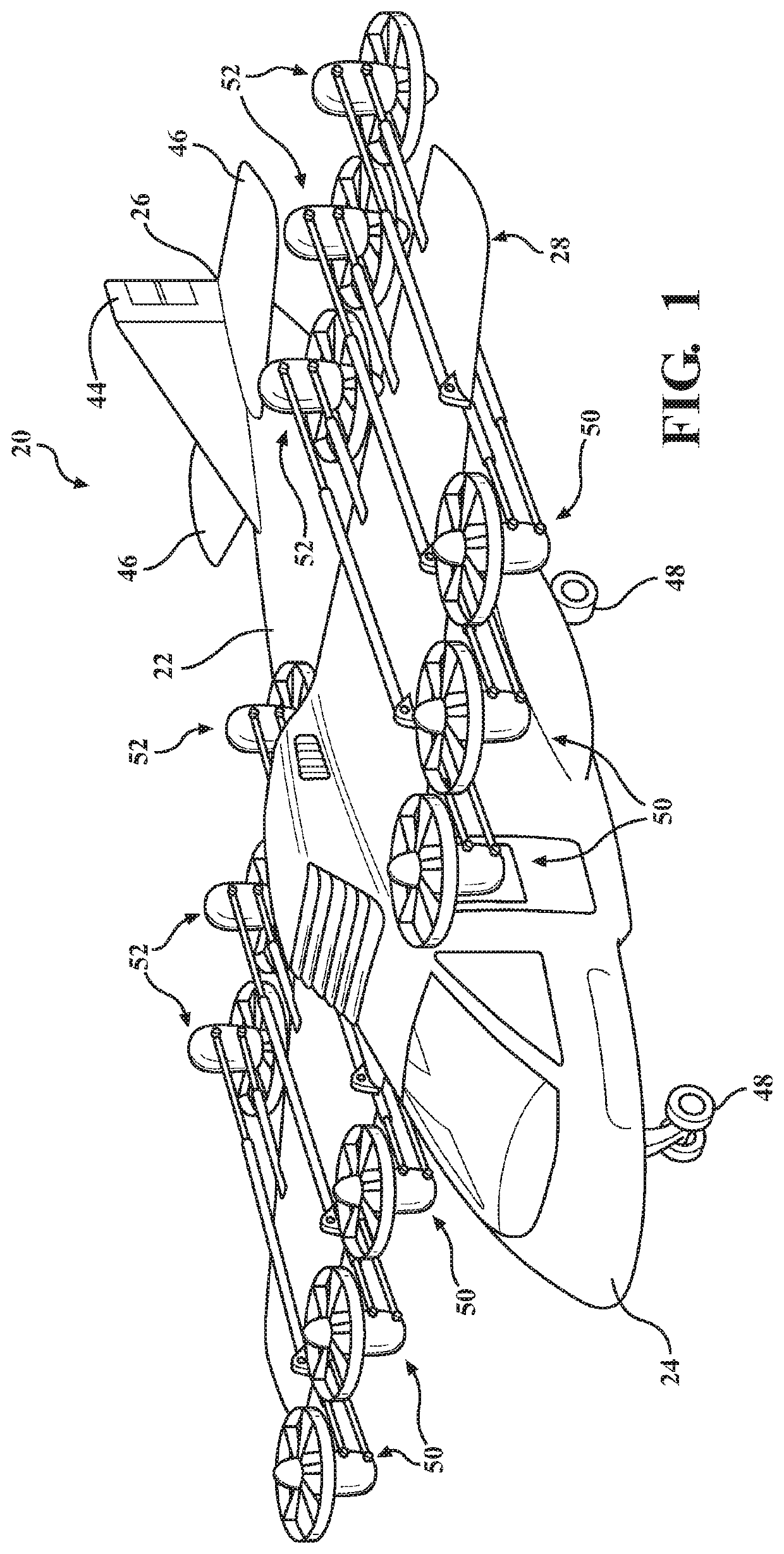
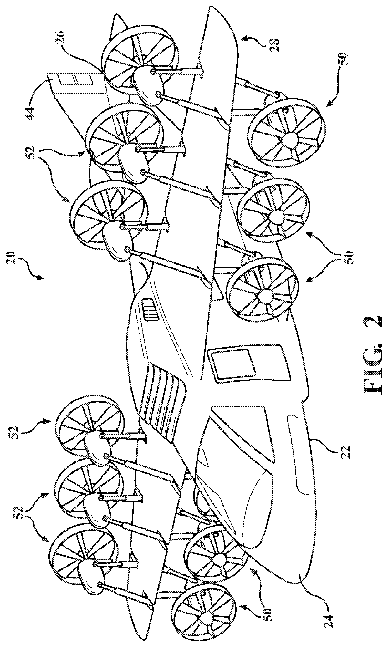
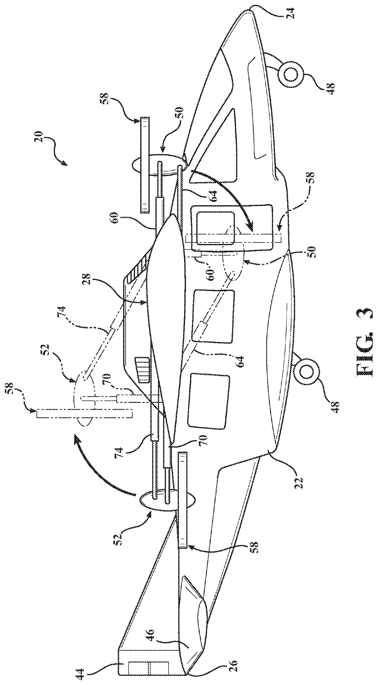
[0034]An exemplary fixed wing aircraft assembly is generally shown at 20 in FIGS. 1-3. The aircraft assembly 20 is of the type capable of vertical take-off and landing (VTOL) maneuvers and forward flight. FIG. 1 shows the aircraft 20 configured for VTOL maneuvers, whereas FIG. 2 shows the aircraft 20 configured for forward flight.

[0035]The aircraft 20 may take many different forms and is shown in FIGS. 1-3 as having a somewhat conventional airframe comprised an elongated fuselage 22 extending between nose 24 and tail 26 ends. The airframe includes at least one main wing, generally indicated at 28. The main wing 28 is fixed to the fuselage 22 between the nose 24 and tail 26 ends. The main wing 28 can, of course, take a wide variety of forms. In one contemplated embodiment (not shown) the main wing 28 is part of a multi-wing set, e.g. a bi-plane or tri-wing plane configuration. In another contemplated embodiment (not shown) the main wing 28 is mounted under the fuselage rather than ab...


PUM


Abstract

A VTOL fixed wing aircraft capable of high-speed forward flight. The aircraft has a main wing internally reinforced with front and aft spars. Spar boxed are located in roll-balanced locations along the wing. Each spar box serves as a connection point for a support linkage that supports a leading-edge and trailing-edge propulsion unit. The leading-edge propulsion unit is fitted with a puller propeller and designed for articulated movement between a VTOL position in front of the wing leading edge and a forward flight position below the wing leading edge. The trailing-edge propulsion unit is fitted with a pusher propeller and designed for articulated movement between a VTOL position in behind the wing trailing edge and a forward flight position above the wing leading edge. The propeller includes a propulsor thrust ring having an aerodynamic profile and a thrust nozzle to capture and vector radial air leakage into thrust.

Description

CROSS REFERENCE TO RELATED APPLICATIONS[0001]This application claims priority to U.S. Provisional Patent Application 62 / 659,869 filed on Apr. 19, 2018, the entire disclosure of which is hereby incorporated by reference and relied upon.BACKGROUND OF THE INVENTIONField of the Invention[0002]The invention relates generally to vertical take-off and landing (VTOL) fixed wing aircraft and propulsion units therefor.Description of Related Art[0003]Transportation is fundamental to connect people, business and services. Since the early days of aviation, designers and engineers in both the commercial and military aerospace fields have envisioned fixed wing aircraft capable of taking off from a runway no larger than its own shadow, and then transitioning to high speed forward flight. However, the reality of vertical take-off and landing (VTOL) flight for high performance commercial aircraft and military fighters have proven to be a perplexing and obsessive goal. Helicopters and Autogyros, both ...

Claims


Application Information

Patent Timeline
IPC IPC(8): B64C29/00
CPCB64C29/0033B64C27/22B64C29/02B64C27/52B64C29/00B64C27/28B64C27/26
Inventor HYMER, JEFFREY
Owner HI LITE AIRCRAFT
Why Eureka
Try Eureka