
Driving force distribution device

Active Publication Date: 2021-03-11
JTEKT CORP
View PDF0 Cites 0 Cited by
  • Summary
  • Abstract
  • Description
  • Claims
  • Application Information

AI Technical Summary

Benefits of technology

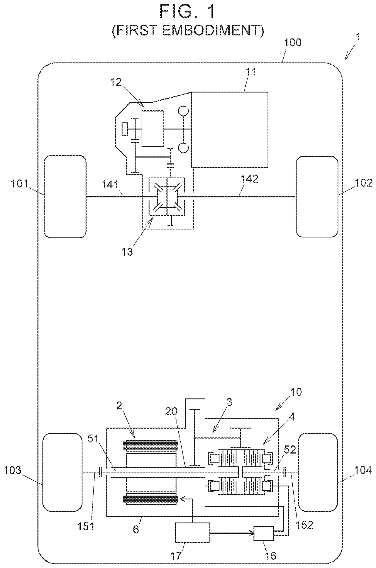
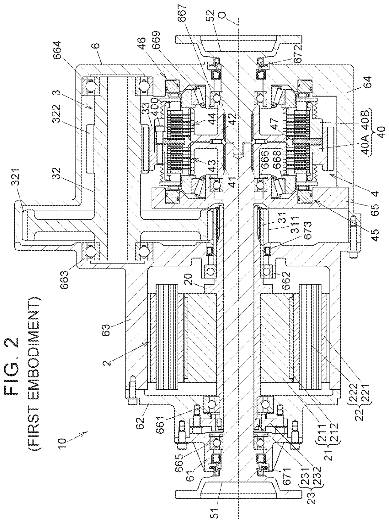
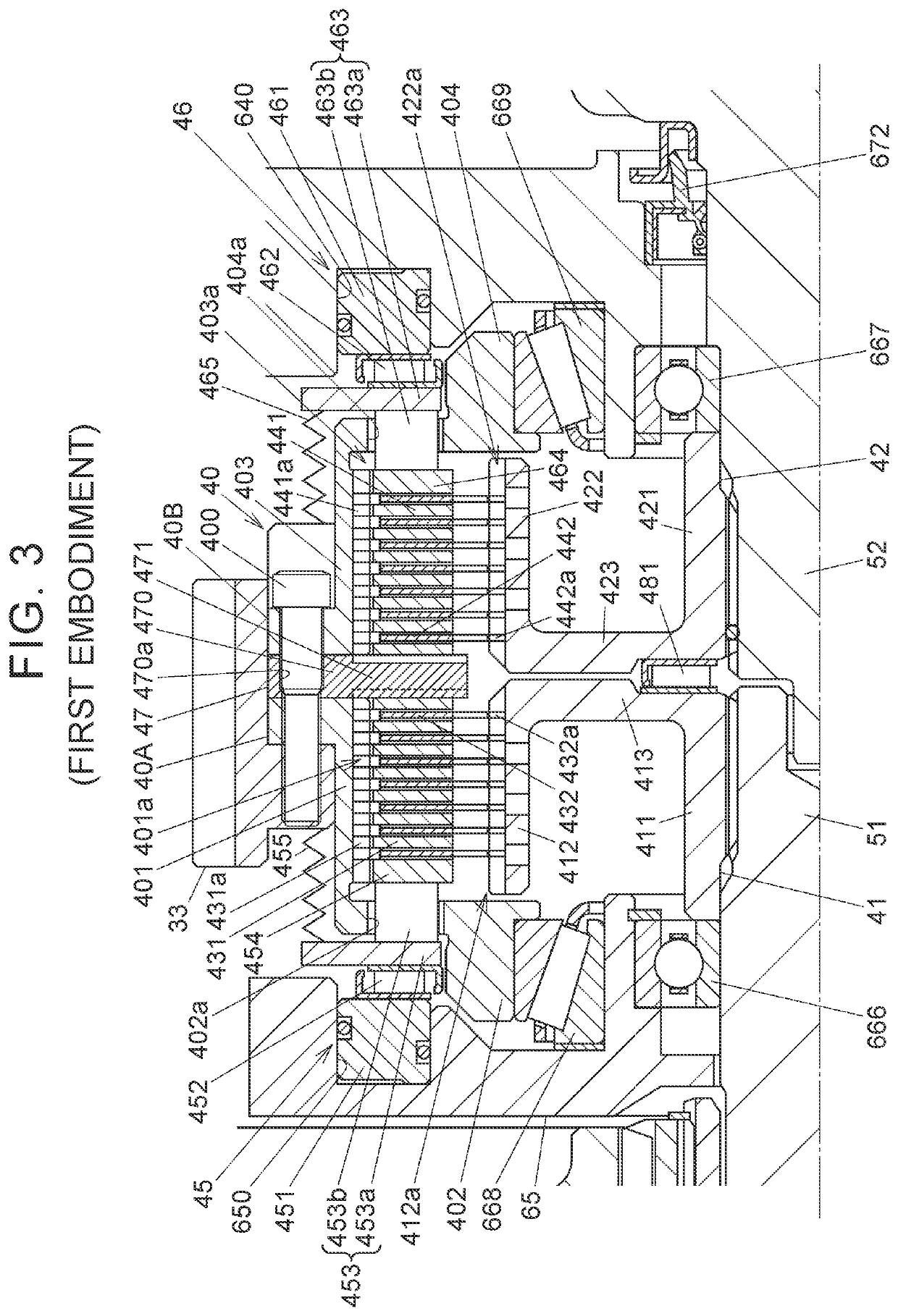
The invention provides a driving force distribution device that prevents the device from becoming too big and interfering with other components, which can decrease fuel efficiency and make it harder to mount in vehicles. This is achieved by restraining the device from being upsized and preventing interference between the pressing forces of multiple disc clutches.

Problems solved by technology

Further, a large mounting space is required, so that the mountability to a vehicle also decreases.

Method used


Image

  • Driving force distribution device
  • Driving force distribution device
  • Driving force distribution device

Examples


first embodiment

Modification of First Embodiment

[0061]Next will be described a modification of the first embodiment with reference to FIGS. 5A to 5C. The modification is obtained by modifying the configuration of the center plate 47 of the first embodiment.

[0062]FIG. 5A is a perspective view illustrating a side face, on the first multiple disc clutch 43 side, of a center plate 47A according to the modification. FIG. 5B is a perspective view illustrating a side face, on the second multiple disc clutch 44 side, of the center plate 47A. FIG. 5C is an explanatory view illustrating a state where the center plate 47A is viewed from a central part side.

[0063]Similarly to the center plate 47 according to the first embodiment, the center plate 47A integrally includes the annular base portion 470 fixed to the input rotational member 40, and the first projecting pieces 471 and the second projecting pieces 472 projecting radially from the base portion 470. The first projecting pieces 471 are divided from the s...

second embodiment

[0067]Next will be described a second embodiment of the present disclosure with reference to FIGS. 6, 7A, and 7B.

[0068]FIG. 6 is a sectional view illustrating an exemplary configuration of a driving force distribution device 7 according to the second embodiment of the present disclosure. FIG. 6 illustrates a part of the driving force distribution device 7 above the rotation axis O, together with its peripheral part.

[0069]The driving force distribution device 7 includes: first and second output rotational members 71, 72 placed to rotate relative to each other around the rotation axis O on the same axis; an input rotational member 70 placed to rotate relative to the first and second output rotational members 71, 72; a first multiple disc clutch 73 placed between the input rotational member 70 and the first output rotational member 71; a second multiple disc clutch 74 placed between the input rotational member 70 and the second output rotational member 72; a first pressing mechanism 75...


PUM


Abstract

A driving force distribution device includes a first output rotational member and a second output rotational member, an input rotational member, a first multiple disc clutch, a second multiple disc clutch, a pressure receiving member, a first pressing mechanism and a second pressing mechanism. The pressure receiving member includes an annular base portion and a plurality of projecting pieces, the projecting pieces include a plurality of first projecting pieces and a plurality of second projecting pieces. The first projecting pieces each have a first pressure receiving surface, the second projecting pieces each have a second pressure receiving surface.

Description

CROSS-REFERENCE TO RELATED APPLICATION[0001]This application claims priority to Japanese Patent Application No. 2019-164381 filed on Sep. 10, 2019, incorporated herein by reference in its entirety.BACKGROUND1. Technical Field[0002]The present disclosure relates to a driving force distribution device configured to output an input driving force by distributing the driving force into first and second output rotational members.2. Description of Related Art[0003]In the related art, a driving force distribution device configured to output an input driving force by distributing the driving force into first and second output rotational members is used to distribute the driving force into a pair of right and left auxiliary driving wheels in a four-wheel drive vehicle, for example (see WO 2011 / 089825, for example).[0004]The driving force distribution device (a power transmission device) described in WO 2011 / 089825 includes: right and left output shafts configured to output a driving force to ...

Claims


Application Information

Patent Timeline
IPC IPC(8): B60K17/02F16D13/52F16D21/00F16D13/70
CPCB60K17/02F16D13/70F16D21/00F16D13/52F16D25/0638B60K1/00B60K17/356B60K17/354B60Y2400/424B60Y2200/92B60K5/04B60K2023/043B60K23/04F16D2021/0661F16D25/10F16D25/082
Inventor FUJII, NORIYUKI
Owner JTEKT CORP
Learn More