
Rare earth magnets

a technology magnets, applied in the field of rare earth magnets, can solve the problems of impaired stability of rsub>2/sub>fe/sub>14/sub>b type crystal structure, and achieve the effect of increasing the crystal structure of a magnetic phase and improving the saturation magnetization

Active Publication Date: 2021-03-04
TOYOTA JIDOSHA KK +1
View PDF0 Cites 1 Cited by
  • Summary
  • Abstract
  • Description
  • Claims
  • Application Information

AI Technical Summary

Benefits of technology

The rare earth magnet described in this patent has the ability to expand its crystal structure to improve its saturation magnetization at high temperatures. By substituting part of Fe with Co and part of Nd with Ce, the magnet can have a single phase and enjoy improved performance. The contents of the magnet's components, Nd, La, Ce, and Co, are determined through first principles calculations.

Problems solved by technology

However, there are also reports that the stability of the R2Fe14B type crystal structure is impaired by substituting part of Fe with Co.

Method used


Image

  • Rare earth magnets
  • Rare earth magnets
  • Rare earth magnets

Examples


examples

[Examples]

[0147]The rare earth magnet of the present disclosure will be described in more detail by way of Examples. The rare earth magnet of the present disclosure is not limited to the conditions used in the following Examples.

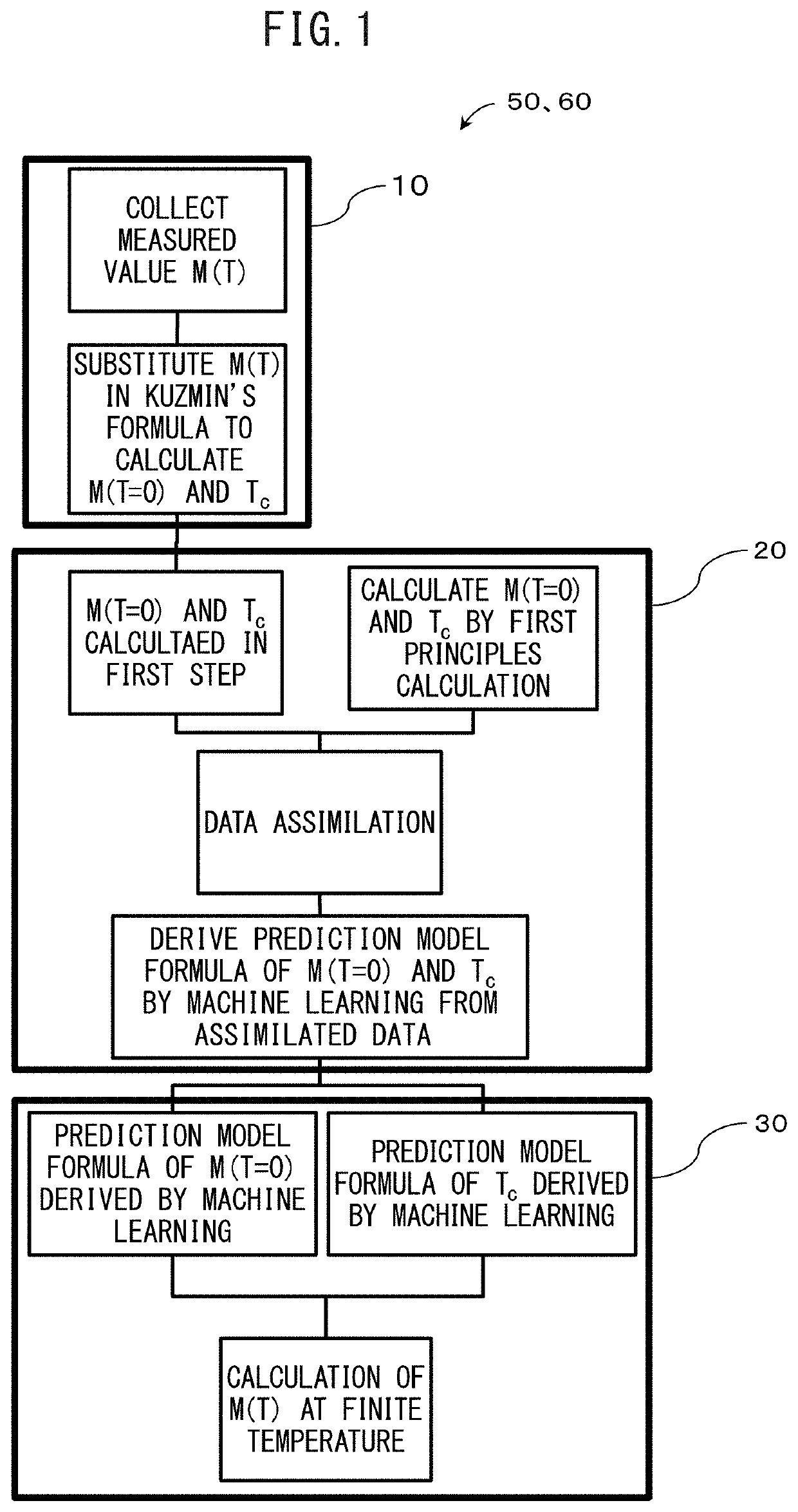
[0148]With respect to the rare earth magnet including a magnetic phase having the composition represented by (Nd(1−x−y)LaxCey)2(Fe(1−z)Coz)14B, the following was performed. Using the measured values of Example 1 and Example 2, and Comparative Example 1 and Comparative Example 2 shown in Table 5, the formulas (1) to (3) were obtained through the first step, the second step, and the third step mentioned above.

TABLE 5SaturationSaturationmagnetizationmagnetizationat 453 Kat z = 0LaCeCoM(x, y, z , T = 453)M(x, y, z = 0, T = 453)Type of datacontent xcontent ycontent z(T: Tesla)(T: Tesla)GainExample 1Measured value0.330.330.301.151.040.11Example 2Measured value0.500.500.301.160.920.24Example 3Data assimilation0.330.330.101.091.040.05Example 4Data assimilation0.330....


PUM

PropertyMeasurementUnit
volume fractionaaaaaaaaaa
temperatureaaaaaaaaaa
Tc(aaaaaaaaaa

Abstract

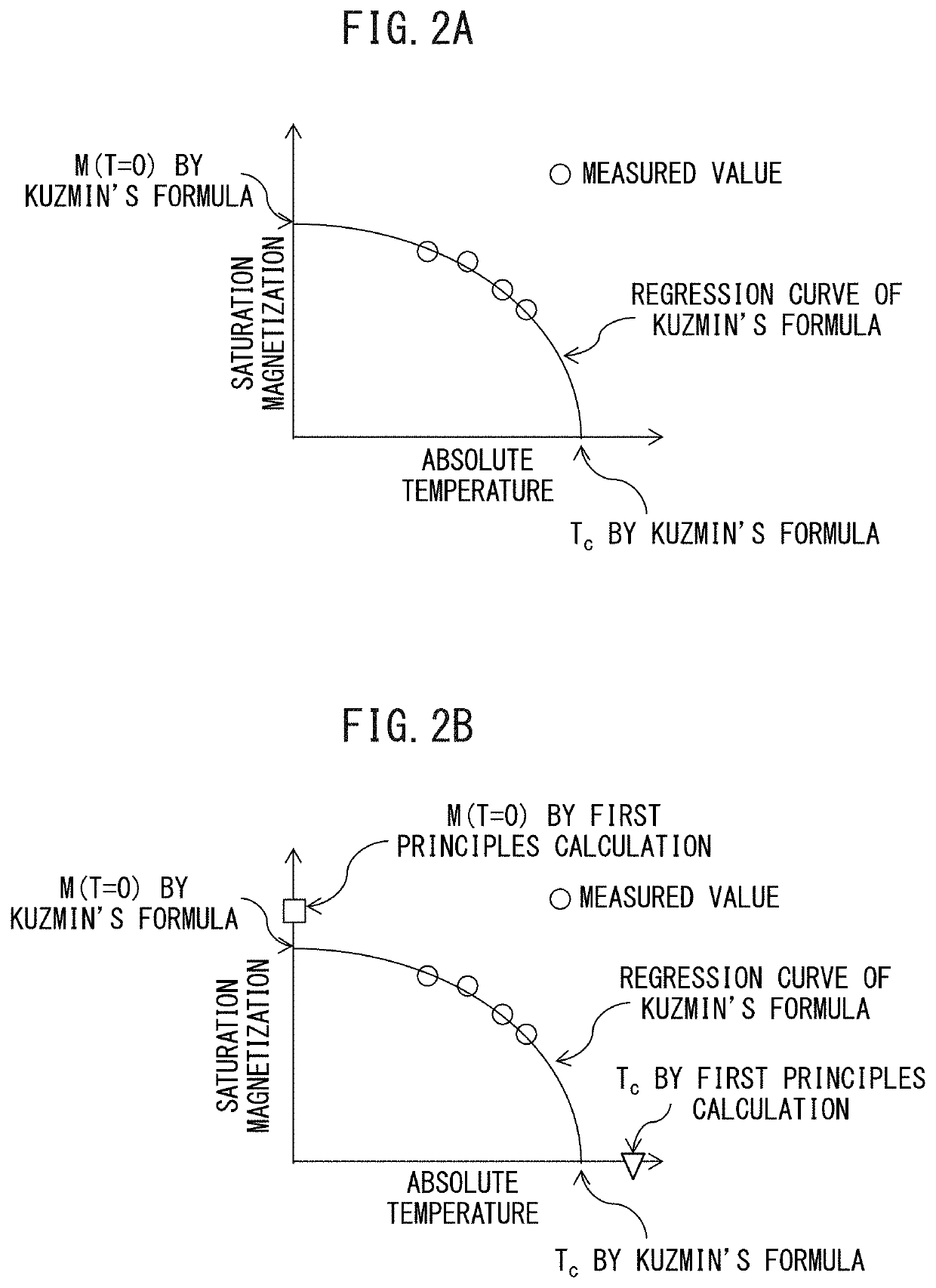
A rare earth magnet including a magnetic phase having the composition represented by (Nd(1−x−y)LaxCey)2(Fe(1−z)Coz)14B. When the saturation magnetization at absolute zero and the Curie temperature calculated by Kuzmin's formula based on the measured values at finite temperature and the saturation magnetization at absolute zero and the Curie temperature calculated by first principles calculation are respectively subjected to data assimilation. The saturation magnetization M(x, y, z, T=0) at absolute zero and the Curie temperature obtained by machine learning using the assimilated data group are applied again to Kuzmin's formula and the saturation magnetization at finite temperature is represented by a function M(x, y, z, T), x, y, and z of the formula in an atomic ratio are in a range of satisfying M(x, y, z, T)>M(x, y, z=0, T) and 400≤T≤453.

Description

TECHNICAL FIELD[0001]The present disclosure relates to rare earth magnets. The present disclosure particularly relates to a single-phase magnetic phase having an R2Fe14B type (R is a rare earth element) crystal structure.BACKGROUND ART[0002]Of rare earth magnets, rare earth magnets including a magnetic phase having an R2Fe14B type crystal structure have been known as high-performance permanent magnets. However, in recent years, there has been an increasing demand for improving the performance of permanent magnets, especially for further improving the saturation magnetization at high temperature.[0003]It is commonly believed that there is a close relationship between the saturation magnetization at high temperature and the Curie temperature. Therefore, in order to improve the saturation magnetization at high temperature, an attempt has been made to raise the Curie temperature by substituting part of Fe with Co in a rare earth magnet including a magnetic phase having an R2Fe14B type c...

Claims


Application Information

Patent Timeline
Patent Type & Authority Applications(United States)
IPC IPC(8): H01F41/02H01F1/053
CPCH01F41/026H01F1/053H01F41/0293H01F1/0575H01F1/0577C22C38/005C22C38/002C22C38/10C22C2202/02
Inventor YOKOTA, KAZUYASYOJI, TETSUYASAKUMA, NORITSUGUMIYAKE, TAKASHIHARASHIMA, YOSUKEAKAI, HISAZUMIKAWASHIMA, NAOKITAMAI, KEIICHIMATSUMOTO, MUNEHISA
Owner TOYOTA JIDOSHA KK
Learn More