Method for pressurized leak testing

a leak detection and pressurized technology, applied in the direction of fluid loss/gain rate measurement, fluid tightness measurement, instruments, etc., can solve the problems of not being able to detect the actual leak point, all testing devices leak to some degree, and no testing device is truly completely helium leak tight, etc., to minimize operator influence and interpretation, the effect of large pressure differential

Active Publication Date: 2021-02-11
ADVANCED PRESSURE TECH
View PDF11 Cites 2 Cited by
  • Summary
  • Abstract
  • Description
  • Claims
  • Application Information

AI Technical Summary

Benefits of technology

The patent describes a method to check for leaks on a device by using a pressure difference between the inside and outside of the device. Helium gas is applied to the outside of the device at a high pressure, while the inside of the device is left in a vacuum. This method helps to detect leaks without leaving any remaining helium in the device, minimizing the impact on the operator and interpretation of the results.

Problems solved by technology

No testing device is truly completely Helium leak tight.
All testing devices leak to some degree.
This method may or may not be able to detect the actual leak point.
The limitation of this test method is the background reading of Helium in the air which is nominally in the range of 10−5 atm cc / sec.
A limitation to outboard sniffer probe testing is that a leak rate below the background level of Helium in the air will not be detected.
There are several disadvantages to the outboard Helium bell jar method.
Using a chamber or jar to evacuate the outside of the device under test, does not disclose a leak point, only that a leak exists.
1. needs to fit in a vacuum chamber which means testing large manifolds or gas piping systems is not practical; and
2. when this method detects a leak, the location of the leak is unknown and could simply be a test fitting connection, not the device actually leaking.
If it detects Helium, the device under test has a leak.
Downsides to this method are that it uses a large volume of Helium which is in scarce supply, cannot locate a leak point and device under test needs to fit in a chamber capable of being pressurized.
To complicate things further, leaks are pressure and time dependent.
An individual might first think the inboard test was done incorrectly because the device under test failed a lower sensitivity sniffer probe test.
Another drawback to Helium outboard testing is the Helium itself.
The higher the pressure and longer the time, the more difficult it is to remove the Helium that permeates (penetrates) into the seat material.
An inboard test performed after an outboard test can (and often does) yield a false failure due to high residual Helium from the previous test.
Helium leak detectors are more sensitive and more expensive than air based test methods, thus Helium leak detectors are reserved for the most critical assemblies.
Chamber methods can quantify the magnitude of the leak, but they cannot pinpoint its location.
Sniffer probe methods can identify the source of the leak, but they cannot quantify how much the assembly is leaking.
Lapses in process control will lead to false positives, false negatives and frustration.
Helium is extremely clingy, it will stick to dust particles.
System leaks or poor venting practices can cause the background level of Helium to rise above 5 parts per million, which could lead to false positive tests.
In view of shrinking supplies and rising demand, the price of Helium has risen sharply since 2007.

Method used


Image

  • Method for pressurized leak testing
  • Method for pressurized leak testing
  • Method for pressurized leak testing

Examples


Embodiment Construction

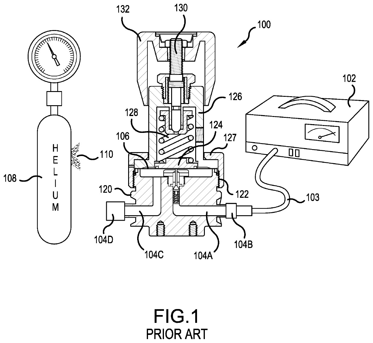
[0052]The present method places a vacuum on the interior of a device under test and only pressurizes a very small volume on a predetermined area on the outside of the device. Thus, the method according to the present invention uses very little Helium. In addition, if the device under test leaks an individual will know where the leak is located. The present invention provides at least the following advantages:

[0053]1. use of a small volume of Helium;

[0054]2. ability to determine the location of the leak; and

[0055]3. Testing of devices or joints in a large manifold or in configuration not suitable for vacuum bell jar.

[0056]It would be impossible in a prior art testing device to put an entire manifold or piping system in a pressure chamber. According to the method of the present invention, the device under test can be tested after installation. The prior art chamber method does not permit testing after installation. The equipment to test of the present invention may be installed in pip...


PUM


Abstract

A method for testing a device under test includes the steps of applying a vacuum to an interior of the device under test. Pressurizing a predetermined portion on an exterior of the device under test with Helium to detect a potential pressure leak. Utilizing a large pressure differential during the exterior testing of the device under test as compared to the vacuum applied during to the interior of the device under test. Detecting a potential leak in the device under test while leaving no residual Helium in a wetted area of the device under test.

Description

BACKGROUND OF THE INVENTIONField of the Invention[0001]The present invention is directed to a method for detecting a leak wherein a device under test is connected to a leak detector with a vacuum applied inside the device under test and Helium under pressure is applied to a specific predetermined area outside the device under test.Description of Background Art[0002]No testing device is truly completely Helium leak tight. All testing devices leak to some degree. Four main leak test methods are typically used to test leak integrity of high purity (HP) and ultra high purity (UHP) gas delivery devices:[0003]1. pressure decay,[0004]2. inboard Helium,[0005]3. outboard Helium sniffer probe, and[0006]4. outboard Helium bell jar.[0007]Each of the above leak test methods has advantages and disadvantages. Realistically, the leak test methods identified above establish the leak integrity of the device under test or system under test rather than to provide a given leak rate per se.Pressure Decay...

Claims


Application Information

Patent Timeline
IPC IPC(8): G01M3/28F17D5/02G01M3/22
CPCG01M3/2861G01M3/22F17D5/02G01M3/222G01M3/224
Inventor MANNELLA, GREGORY JOHNMEYER, CHRISTOPHER NEIL
Owner ADVANCED PRESSURE TECH
Why Eureka
Try Eureka