Apparatus And Method For Laser Processing A Material

a technology of material laser and apparatus, applied in the direction of optical elements, manufacturing tools, instruments, etc., can solve the problems of increasing processing costs, slowing down the construction of larger structures, and expensive external optics with such flexibility

Active Publication Date: 2021-02-04
TRUMPF LASER UK LTD
View PDF0 Cites 2 Cited by
  • Summary
  • Abstract
  • Description
  • Claims
  • Application Information

AI Technical Summary

Benefits of technology

The invention relates to an optical fibre that has a homogeneous core, which prevents unintentional mode coupling between optical modes. The use of a homogeneous core optical fibre avoids mode diffusion, which means optical modes do not spread into other optical modes when the fibre is bent or coiled. This prevents difficulties with industrial material processing applications such as cutting, welding, drilling, marking and engraving. The invention allows for stable optical mode output from the optical fibre and can be used in industrial laser systems.

Problems solved by technology

However, providing external optics with such flexibility is expensive, and having to change the working distance takes time and therefore increases the costs of processing.
However, the use of the fundamental Gaussian mode means that it is slow to build larger structures.
A problem that can occur with laser drilling is the laser beam damaging surfaces behind the hole once it has been drilled.
However, such beams can diverge rapidly and do not preserve their annular cross-section beyond 1 mm to 2 mm away from focus.
The metal oxides can cause problems such as weakening welded parts, reduction of the corrosive properties of the stainless steel owing to a depletion of chromium on the cut-edge faces, and increased wear on sliding parts owing to the increased hardness of the metal oxides compared to stainless steel.
This has limited benefit since a laser having constant laser beam quality will have a fixed relationship between the focal spot size and divergence, with this fixed relationship working in the opposite way to that desired by the cutting process regimes.
It is therefore not possible to optimize process parameters for all metal types and thicknesses.
High intensity of the laser beam is preferably for increasing cutting speed, but this can be at the expense of melt flow dynamics which can cause undesirable striations of the top surface of the cut.
Similar limitations arise with other material processing equipment, such for example as welding, marking, and additive manufacturing.
Such diffusion is undesirable in industrial material processing applications such as cutting, welding, drilling, marking and engraving.

Method used


Image

  • Apparatus And Method For Laser Processing A Material
  • Apparatus And Method For Laser Processing A Material
  • Apparatus And Method For Laser Processing A Material

Examples


Embodiment Construction

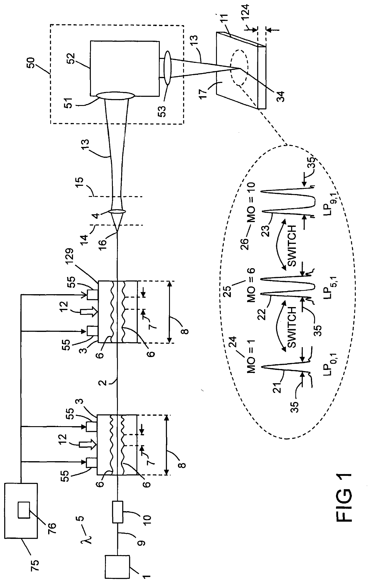
[0105]FIG. 1 shows apparatus for laser processing a material 11, which apparatus comprises an optical fibre 2, at least one squeezing mechanism 3, and a lens 4, wherein:[0106]the optical fibre 2 is a multimode optical fibre;[0107]the optical fibre 2 is such that laser radiation 13 is able to propagate along the optical fibre 2 in a first optical mode 21 and in a second optical mode 22;[0108]the squeezing mechanism 3 comprises at least one periodic surface 6 defined by a pitch 7; and[0109]the periodic surface 6 is located adjacent to the optical fibre 2; and the apparatus is characterized in that:[0110]the pitch 7 couples the first optical mode 21 and the second optical mode 22 together;[0111]the first optical mode 21 is defined by a first mode order 24, and the second optical mode 22 is defined by a second mode order 25 which is higher than the first mode order 24;[0112]the squeezing mechanism 3 is configured to squeeze the periodic surface 6 and the optical fibre 2 together with a ...


PUM

PropertyMeasurementUnit
Lengthaaaaaaaaaa
Lengthaaaaaaaaaa
Lengthaaaaaaaaaa

Abstract

Apparatus for laser processing a material (11), which apparatus comprises an optical fibre (2), at least one squeezing mechanism (3), and a lens (4), wherein: the optical fibre (2) is a multimode optical fibre; the optical fibre (2) is such that laser radiation (13) is able to propagate along the optical fibre (2) in a first optical mode (21) and in a second optical mode (22); the squeezing mechanism (3) comprises at least one periodic surface (6) defined by a pitch (7); and the periodic surface (6) is located adjacent to the optical fibre (2); and the apparatus is characterized in that: the pitch (7) couples the first optical mode (21) and the second optical mode C(22) together; the first optical mode (21) is defined by a first mode order (24), and the second optical mode (22) is defined by a second O mode order (25) which is higher than the first mode order (24); the squeezing mechanism (3) is configured to squeeze the periodic surface (6) and the optical fibre (2) together with a squeezing force (12), thereby coupling the first optical mode (21) to the second optical mode (22); the lens (4) is defined by a front focal plane (14) and a rear focal plane (15); the first optical mode (21) is defined by a Rayleigh length (217); and the lens (4) is located within two of the Rayleigh lengths (217) from the distal end (16) of the optical fibre (2).

Description

FIELD OF INVENTION[0001]This invention relates to an apparatus and method for laser processing a material.BACKGROUND TO THE INVENTION[0002]Lasers are used in many laser processing applications including cutting, welding, drilling, engraving, and additive manufacturing. In these applications, it is often desirable to optimize the size and cross-sectional profile of the laser beam that is interacting with the material. For example, the spot size of the laser beam interacting with the material can be changed by changing the working distance between a focusing lens and a work piece. The cross-sectional profile can be changed from Gaussian to top hat, or to an annular or ring profile using external optics. However, providing external optics with such flexibility is expensive, and having to change the working distance takes time and therefore increases the costs of processing. It would be desirable to be able to change the laser beam from a single Gaussian fundamental mode to a top hat or...

Claims


Application Information

Patent Timeline
IPC IPC(8): B23K26/342B23K26/073B23K26/38B22F3/105B23K26/06B22F3/24
CPCB23K26/342B23K26/0734B23K26/38B33Y10/00B23K26/0648B22F3/24B22F2003/247B22F3/105B23K26/06B23K26/073B23K26/34B23K26/21G02B27/0994G02B6/4296G02B6/3624G02B6/268Y02P10/25B33Y30/00B33Y40/20G02B6/14
Inventor MALINOWSKI, ANDREWCODEMARD, CHRISTOPHE ANDREZARVAS, MIKHAIL NICKOLAOSBOTHEROYD, IAINKEEN, STEPHEN JOHNVARNHAM, MALCOLM PAUL
Owner TRUMPF LASER UK LTD
Why Eureka
Try Eureka