
Method for producing vehicle wheels

a vehicle wheel and production method technology, applied in the direction of manufacturing tools, transportation and packaging, planing/slotting apparatus, etc., can solve the problems of dull gloss, lathes that do not enable the formation of bright surfaces on three-dimensional surfaces, and the inability of buffing to achieve high metallic gloss, high reflectivity, and high metallic gloss appearance

Active Publication Date: 2021-01-28
RAYS ENGINEERING
View PDF22 Cites 1 Cited by
  • Summary
  • Abstract
  • Description
  • Claims
  • Application Information

AI Technical Summary

Benefits of technology

The present invention provides a method for producing vehicle wheels with a high metallic gloss appearance and excellent design properties. The method involves continuously cutting processing the surface of a wheel body with a cutting tool three-dimensionally and automatically forming a smooth surface with no cutting trace. This processed surface has a high reflectance and metallic gloss property, similar to that of a mirror, and is suitable for viewing from various directions. The invention allows for the formation of a specular glossy surface in a processed groove that cannot be obtained by buffing, making it suitable for use on a three-dimensional shape surface of a design surface.

Problems solved by technology

Unfortunately, cutting processing with a lathe enables a bright surface to be formed only on a specific one surface such as a top surface of a spoke or a rim flange on a design surface side, and buffing does not enable a surface to be finished with a high metallic gloss property like a mirror.
That is, lathe processing is performed to cut a surface of a workpiece by pressing a blade against the workpiece rotating, so that a processing range is limited to a two-dimensional plane that can be easily formed automatically.
For this reason, a lathe does not enable a bright surface to be formed on a three-dimensional surface such as that in a range from a top surface of a spoke to a side surface or an inner peripheral surface of a decorative window.
However, when clear coating is then applied to the surface, countless fine polishing marks appear to result in dull gloss due to characteristics of buffing.
This does not enable the surface to be finished with high gloss like a mirror.
This causes a large number of cutting traces to remain on a cutting surface formed with the end mill, so that the cutting surface cannot be formed with high gloss like a mirror.

Method used


Image

  • Method for producing vehicle wheels
  • Method for producing vehicle wheels
  • Method for producing vehicle wheels

Examples


Embodiment Construction

[0017]Hereinafter, an embodiment of the present invention will be described.

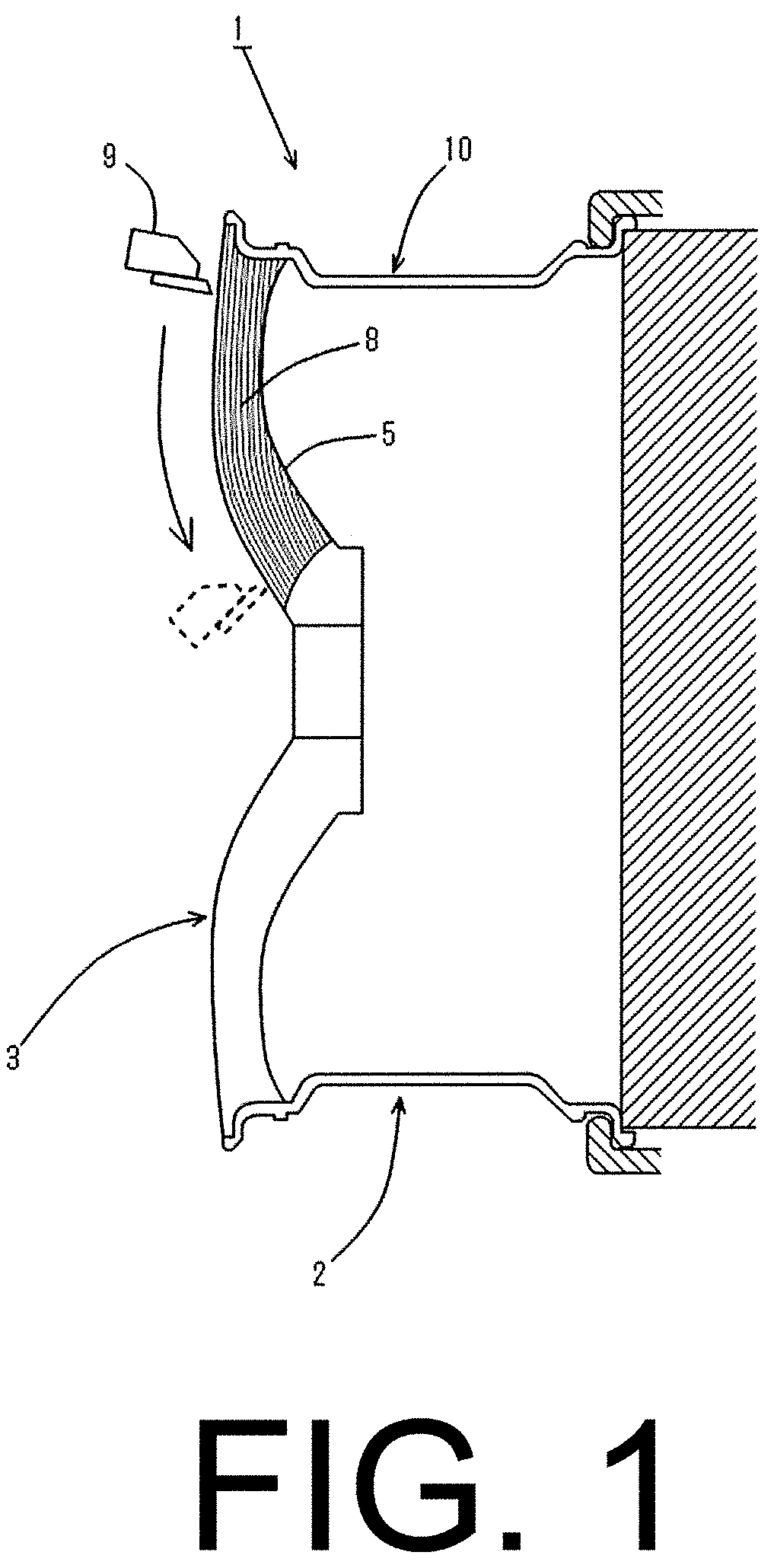
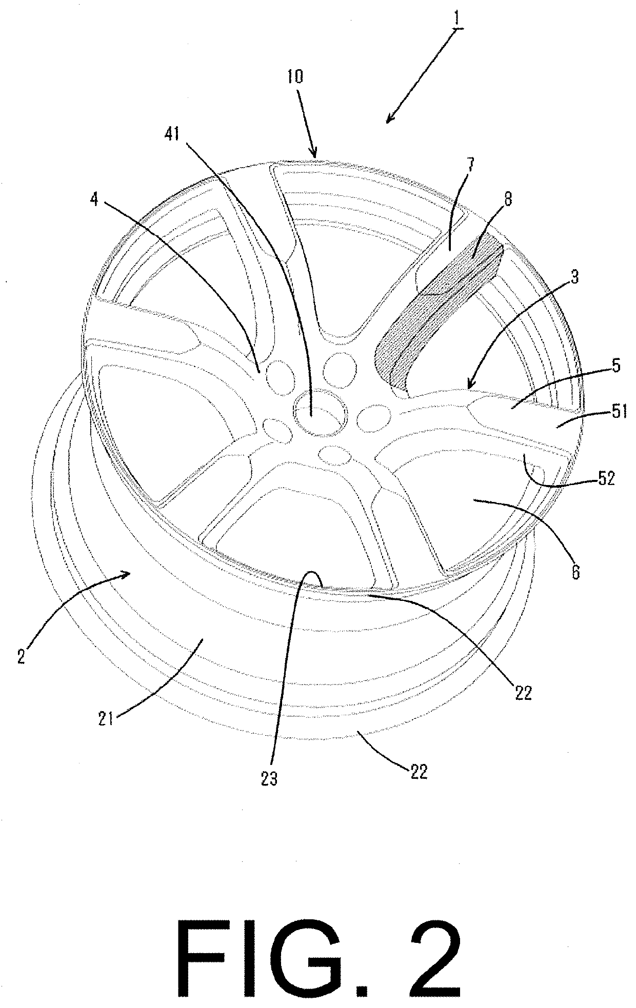
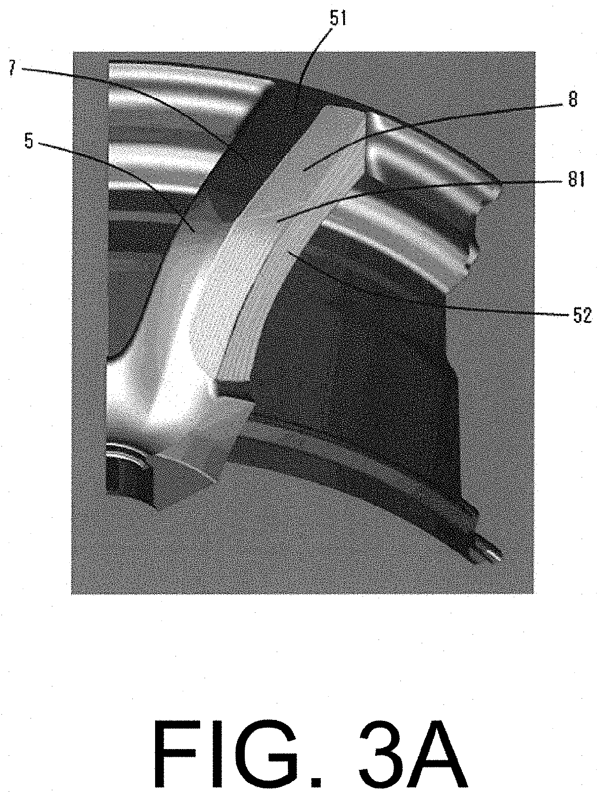
[0018]The present embodiment is a method for forming a specular glossy surface 8 like a mirror, having a high metallic gloss property, by exposing base metal to a three-dimensional shape surface of a design surface of a vehicle wheel 1. That is, the method (referred to as three-dimensional continuous cutting processing as appropriate) is for automatically forming the specular glossy surface 8 in the three-dimensional shape surface, the method being performed such that when the vehicle wheel 1 is manufactured, the three-dimensional shape surface of the design surface of the vehicle wheel 1 is cut with a cutting tool (bite tool) 9 using a processing machine while the cutting tool 9 is moved three-dimensionally and continuously relative to the three-dimensional shape surface, as shown in FIG. 1, to expose the base metal and finish the base metal into a mirror-like processed surface with a high metallic gloss pr...


PUM

PropertyMeasurementUnit
incident angleaaaaaaaaaa
reflectanceaaaaaaaaaa
heightaaaaaaaaaa

Abstract

The step being performed in a state where a wheel body is fixed to be prevented from rotating around a rotation axis while a cutting edge of a cutting tool is in contact with the three-dimensional shape surface of the design surface in the wheel body, the cutting tool being three-dimensionally and continuously moved relatively along the three-dimensional shape surface while being changed in direction with respect to the three-dimensional shape surface to allow a rake face of the cutting tool to face a tool travel direction to perform three-dimensional continuous cutting processing that allows a specular glossy surface to be automatically formed in the three-dimensional shape surface, the specular glossy surface being finished into a processed surface having a high metallic gloss property by exposing the base metal.

Description

BACKGROUND OF THE INVENTIONField of the Invention[0001]The present invention relates to a method for producing vehicle wheels, and more particularly to a method for forming a specular glossy surface like a mirror, having a high metallic gloss property of a base metal on a three-dimensional shape surface of a design surface.Description of the Related Art[0002]Conventionally, a vehicle wheel has a design surface formed with a bright surface in which a base metal is partially exposed to improve design properties.[0003]For example, known examples of a method for forming the bright surface include a method in which a design surface is scraped with an end mill (rotary tool) to expose a base metal, and then buffing is performed to increase brilliancy (refer to Japanese Patent Application Laid-open No. 7-223126, Japanese Patent Application Laid-open No. 6-335854, Japanese Patent Application Laid-open No. 6-71552, and Japanese Patent Application Laid-open No. 7-276148). In addition, when buf...

Claims


Application Information

Patent Timeline
Patent Type & Authority Applications(United States)
IPC IPC(8): B21K1/40
CPCB21K1/40B23B1/00B23B5/02B23D5/00B60B3/00B60B2310/226B60B2310/616B60B2310/656B60B2310/652B60B2310/651Y10T409/50082Y10T29/49536Y10T409/502624Y10T409/5041
Inventor INATANI, SHUJIRO
Owner RAYS ENGINEERING
Learn More