Abnormality determination device and abnormality determination system

a technology of abnormality and determination device, which is applied in the direction of complex mathematical operations, machine learning, instruments, etc., can solve the problems of industrial failure, difficult to take frequent data, abnormal behavior of industrial machines, etc., and achieve the effect of efficient learning and determination

Active Publication Date: 2021-01-21
FANUC LTD
View PDF3 Cites 1 Cited by
  • Summary
  • Abstract
  • Description
  • Claims
  • Application Information

AI Technical Summary

Benefits of technology

The invention described in this patent allows for efficient learning and decision-making by not requiring repetitive data observation at many times.

Problems solved by technology

As the industrial machines continue to be operated on site, abnormality may sometimes occur in the behaviors of the industrial machines due to aging degradations of components of the industrial machines, external factors such as changes in the outdoor air temperature and vibrations, workers' setting mistakes, or the like.
Moreover, depending on the activity of the industrial machine to be detected, it may sometimes be difficult to take frequent data.
For example, a collision or the like may possibly result in a failure of the industrial machine if it is repeated many times, so that it is difficult to frequently take data on such an action.
Nevertheless, if learning is performed based only on data on a specific time, only the specific time data can be used for the normality determination, so that erroneous detection based on noise that is easily noticeable in a global point of view is caused to increase.
As another problem, if a plurality of physical quantities acquired at a plurality of times are learned together, the learning may sometimes include time divisions free of the appearance of normality features.
As a further problem, if operating conditions of the industrial machine, especially driving conditions (rotational frequency, etc.) of a motor for driving the industrial machine, are changed, data such as the torque commands also change.
Therefore, if a model used is created based only on data acquired in a specified operating condition, correct normality determination cannot be achieved for data detected in a different operating condition.
However, operating conditions set for the industrial machine in a manufacturing site vary depending on the purpose and cannot be put together into one.
Also, there are parameters, such as the ambient temperature, that cannot be controlled by the worker's will, and a huge amount of data is required to create models in consideration of all these parameters.

Method used


Image

  • Abnormality determination device and abnormality determination system
  • Abnormality determination device and abnormality determination system
  • Abnormality determination device and abnormality determination system

Examples


first embodiment

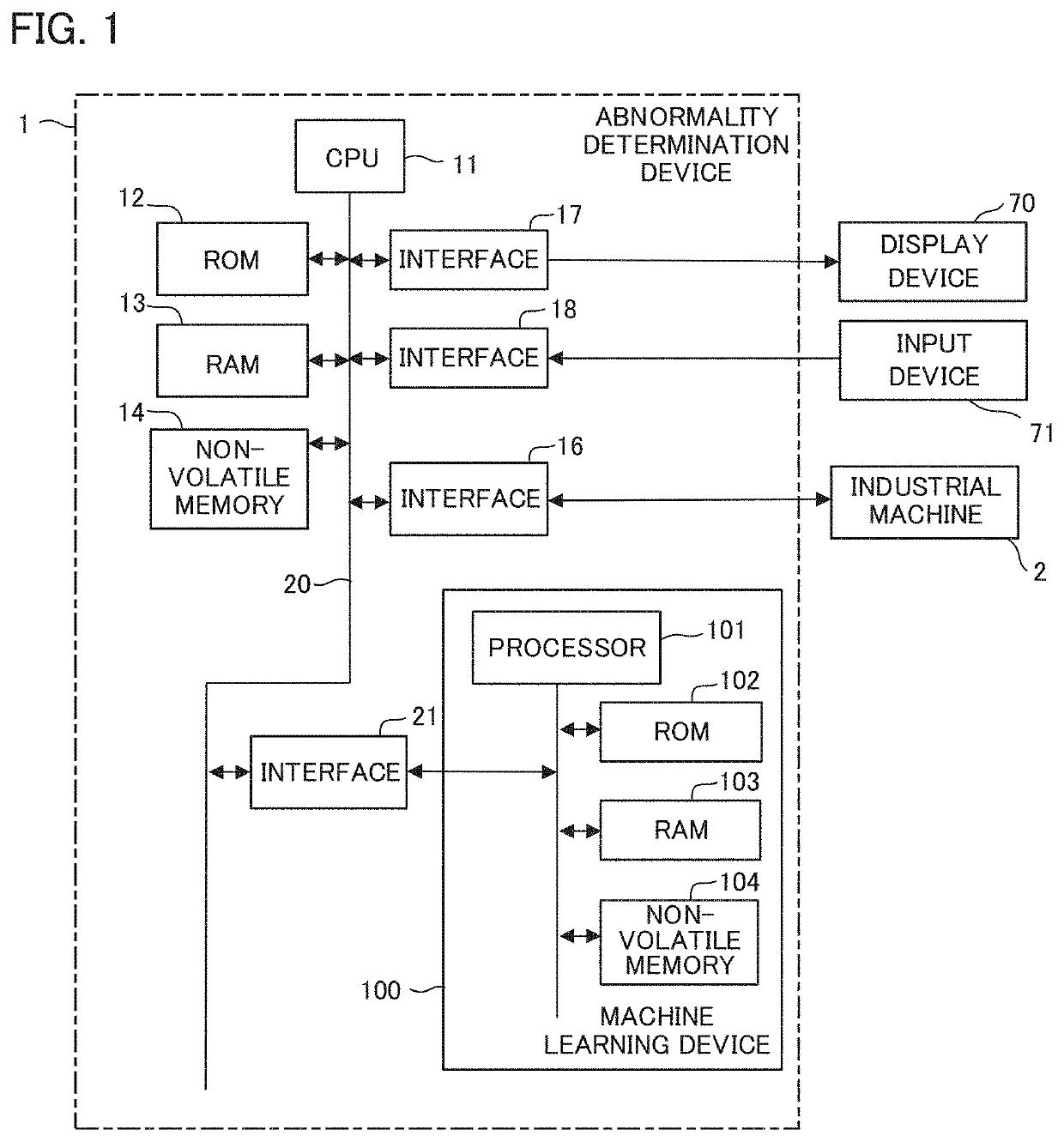
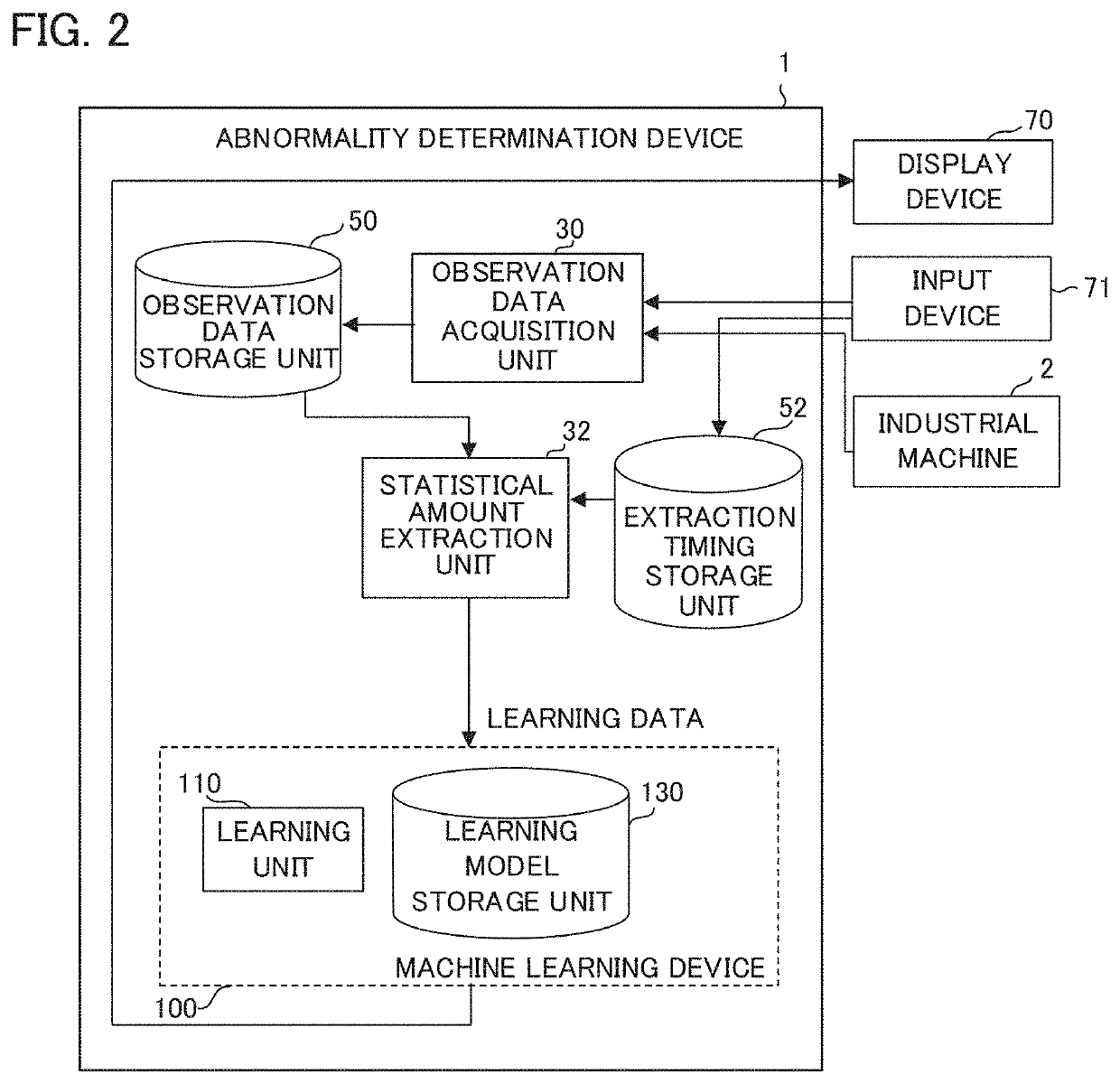
[0043]FIG. 2 is a schematic functional block diagram of an abnormality determination device 1 and a machine learning device 100 according to a

[0044]The abnormality determination device 1 of the present embodiment has a configuration required when the machine learning device 100 learns the operating state of a machine tool (learning mode). Each functional block shown in FIG. 2 is implemented as the CPU 11 of the abnormality determination device 1 and the processor 101 of the machine learning device 100 shown in FIG. 1 execute their respective system programs and control the operation of each part of the abnormality determination device 1 and the machine learning device 100.

[0045]The abnormality determination device 1 of the present embodiment includes an observation data acquisition unit 30 and a statistical amount extraction unit 32, and the machine learning device 100 of the abnormality determination device 1 includes a learning unit 110. Moreover, an observation data storage unit ...

second embodiment

[0054]FIG. 5 is a schematic functional block diagram of an abnormality determination device 1 and a machine learning device 100 according to a

[0055]The abnormality determination device 1 of the present embodiment has a configuration required when the machine learning device 100 diagnoses the operating state of an industrial machine 2 (determination mode). Each functional block shown in FIG. 5 is implemented as the CPU 11 of the abnormality determination device 1 and the processor 101 of the machine learning device 100 shown in FIG. 1 execute their respective system programs and control the operation of each part of the abnormality determination device 1 and the machine learning device 100.

[0056]The abnormality determination device 1 of the present embodiment includes an observation data acquisition unit 30 and a statistical amount extraction unit 32, and the machine learning device 100 of the abnormality determination device 1 includes a machine abnormality determination unit 120. M...

third embodiment

[0060]FIG. 6 is a schematic functional block diagram of an abnormality determination device 1 and a machine learning device 100 according to a

[0061]The abnormality determination device 1 of the present embodiment has a configuration required when the machine learning device 100 learns the operating state of a machine tool (learning mode). Each functional block shown in FIG. 6 is implemented as the CPU 11 of the abnormality determination device 1 and the processor 101 of the machine learning device 100 shown in FIG. 1 execute their respective system programs and control the operation of each part of the abnormality determination device 1 and the machine learning device 100.

[0062]The abnormality determination device 1 of the present embodiment includes an observation data acquisition unit 30, statistical amount extraction unit 32, and correction unit 34, and the machine learning device 100 of the abnormality determination device 1 includes a learning unit 110. Moreover, an observation...


PUM


Abstract

An abnormality determination device acquires observation data observed during an operation of an industrial machine, extracts partial time-series data, including a portion representative of a feature of an operating state at a specified timing, from the observation data, calculates a statistical amount from the extracted partial time-series data, and performs processing for machine learning related to determination of operation abnormality of the industrial machine, based on the calculated statistical amount.

Description

RELATED APPLICATIONS[0001]The present application claims priority to Japanese Patent Application Number 2019-131452 filed Jul. 16, 2019, the disclosure of which is hereby incorporated by reference herein in its entirety.BACKGROUND OF THE INVENTIONField of the Invention[0002]The present invention relates to an abnormality determination device and an abnormality determination system.Description of the Related Art[0003]Industrial machines such as machine tools and robots are installed in factories and other manufacturing sites, and workers are operating these industrial machines to manufacture products. As the industrial machines continue to be operated on site, abnormality may sometimes occur in the behaviors of the industrial machines due to aging degradations of components of the industrial machines, external factors such as changes in the outdoor air temperature and vibrations, workers' setting mistakes, or the like. If the behavior of any of the industrial machines is determined t...

Claims


Application Information

Patent Timeline
Patent Type & Authority Applications(United States)
IPC IPC(8): G05B23/02G06N20/00
CPCG05B23/0218G06N20/00G01D21/02G06F17/18G05B15/02
Inventor HADA, KEITA
Owner FANUC LTD
Why Eureka
Try Eureka