Protection relay
a protection relay and relay technology, applied in the field of protection relays, can solve problems such as the problem of longer response tim
- Summary
- Abstract
- Description
- Claims
- Application Information
AI Technical Summary
Benefits of technology
Problems solved by technology
Method used
Image

Examples
first embodiment
[0037][Configuration Example of Power System]
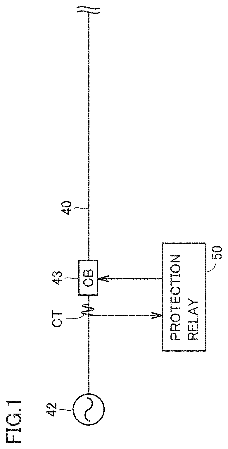
[0038]FIG. 1 shows a configuration example of a power system including a protection relay. Referring to FIG. 1, a power supply 42 is provided at one end of a power transmission line 40. Although power transmission line 40 is a three-phase power transmission line, power transmission line 40 is shown by one line in FIG. 1 for ease of illustration.
[0039]A current transformer CT is provided on power transmission line 40. A circuit breaker (CB) 43 is further provided on power transmission line 40.
[0040]A protection relay 50 obtains, from current transformer CT, a signal indicating a three-phase AC current flowing through power transmission line 40. Protection relay 50 samples the obtained current signal and performs Analog-to-Digital (A / D) conversion of the obtained current signal, to thereby generate current data. The current data may be referred to as “time-series current data”, or simply “time-series data”. Protection relay 50 performs over...
second embodiment
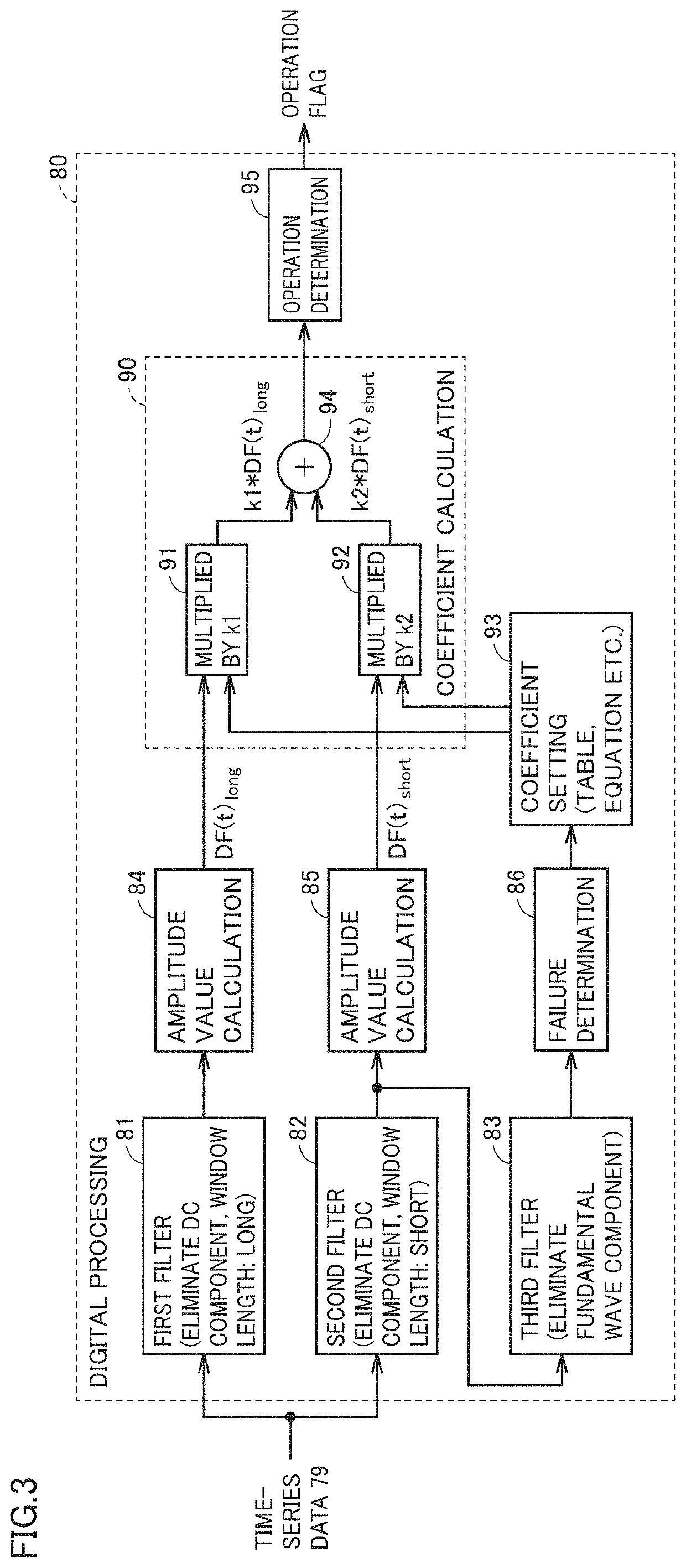
[0084]In a second embodiment, specific examples of first filter 81, second filter 82 and third filter 83 described in the first embodiment, and a specific method for setting coefficients k1 and k2 will be described.
[0085][Specific Examples of First and Second Filters]
[0086](First Filter 81)
[0087]Specifically, a full cycle cosine filter is used as first filter 81. Assuming that relay calculation cycle T is 30° in electrical angle, the full cycle cosine filter is expressed as follows:
i(t)+i(t−1)·cos 30°+i(t−2)·cos 60°+i(t−3)·cos 90°+i(t−4)·cos 120°+i(t−5)·cos 150°+i(t−6)·cos 180°+i(t−7)·cos 210°+i(t−8)·cos 240°+i(t−9)·cos 270°+i(t−10)·cos 300°+i(t−11)·cos 330° (2).
[0088]Therefore, a window length of the full cycle cosine filter is 330° in electrical angle.
[0089]FIG. 6 shows a gain characteristic of the full cycle cosine filter. In FIG. 6, the horizontal axis represents a frequency standardized by a rated frequency f of the power system, and the vertical axis represents a gain. As sho...
third embodiment
[0119]In a third embodiment, another method for setting coefficients k1 and k2 in coefficient calculation unit 90 will be described.
[0120]FIG. 15 shows setting examples of coefficient values k1 and k2 in the third embodiment. In FIG. 15(A), coefficient values k1 and k2 are shown in the form of a table, and in FIG. 15(B), coefficient values k1 and k2 are shown in the form of a graph. In FIG. 15(A), the time elapsed from the failure detection time is shown with respect to relay calculation cycle T (T=30°). Coefficient value k1 is set at 1 and coefficient value k2 is set at 0 until the failure detection time, for example.
[0121]Referring to FIG. 15, when 1T has elapsed from the detection of a failure of the power system, coefficient setting unit 93 in FIG. 3 abruptly decreases coefficient k1 to 0.1 and abruptly increases coefficient k2 to 0.9. Thereafter, coefficient setting unit 93 gradually increases coefficient k1 and gradually decreases coefficient k2 with a lapse of time. As shown ...
PUM
 Abstract
Description
Claims
Application Information
 - R&D
- Intellectual Property
- Life Sciences
- Materials
- Tech Scout
- Unparalleled Data Quality
- Higher Quality Content
- 60% Fewer Hallucinations
Browse by: Latest US Patents, China's latest patents, Technical Efficacy Thesaurus, Application Domain, Technology Topic, Popular Technical Reports.
© 2025 PatSnap. All rights reserved.Legal|Privacy policy|Modern Slavery Act Transparency Statement|Sitemap|About US| Contact US: help@patsnap.com