
Secondary battery separator

a battery separator and secondary battery technology, applied in the field of secondary battery separators, can solve the problems of short circuiting of the electrodes or thermal runaway, and achieve the effects of reducing deformation caused by shrinkage, melting, and small level

Pending Publication Date: 2020-12-31
DAICEL CHEM IND LTD
View PDF1 Cites 3 Cited by
  • Summary
  • Abstract
  • Description
  • Claims
  • Application Information

AI Technical Summary

Benefits of technology

The secondary battery separator described in this patent is a lightweight, durable material that can maintain its shape in high temperatures. It is excellent at resisting shrinkage and melting, which can cause deformation. This means that the secondary battery is safer and less likely to cause short circuits or thermal runaway. It can be used in devices like smartphones and electric vehicles, improving their fuel economy.

Problems solved by technology

Also, in a case where the temperature inside the battery increases even after the flow of lithium ions has been stopped, when the separator contracts (shrinks) or melts (melts down), there is a concern that short circuiting of the electrodes or thermal runaway may occur.

Method used


Image

  • Secondary battery separator
  • Secondary battery separator
  • Secondary battery separator

Examples


example 1

[0105]1.6 parts by weight of sodium carboxymethyl cellulose (CMC, viscosity of 1 wt. % aqueous solution (at 25° C. and 60 rotations): 1724 mPa·s, decomposition temperature: 290° C., reduction ratio with drying: 8.2%, available from Daicel FineChem Ltd., product number: 2200) was added to 100 parts by weight of water, the mixture was stirred for 30 minutes at 2000 rpm using a planetary centrifugal mixer (available from Thinky Corporation, product name: Awatori Rentaro, model number: ARE-310), and a CMC aqueous solution was thereby prepared.

[0106]In addition, 18 parts by weight of water was added to 6 parts by weight of aramid fibers (average thickness: 0.56 μm, average length: 0.43 mm, average aspect ratio: 768, decomposition temperature: 400° C. or higher, 5% weight loss temperature (Td5) measured at a temperature increase rate of 10° C. / min (in nitrogen): 545° C., solid content: 20.7%, available from Daicel FineChem Ltd., trade name: Tiara, product number: KY400S), and the mixture ...

example 2

[0108]A separator (2) (thickness of the heat resistant layer: 7 μm) formed from a heat resistant layer / PP laminate with the heat resistant layer being made from a non-woven fabric containing aramid fibers and CMC was produced in the same manner as in Example 1 with the exception that the coating thickness of the heat resistant layer-forming composition (1) was changed.

example 3

[0109]A separator (3) (thickness of the heat resistant layer: 6 μm) formed from a heat resistant layer / PP laminate with the heat resistant layer being made from a non-woven fabric containing aramid fibers and CMC was produced in the same manner as in Example 1 with the exception that the coating thickness of the heat resistant layer-forming composition (1) was changed.


PUM

PropertyMeasurementUnit
melting pointaaaaaaaaaa
weight loss temperatureaaaaaaaaaa
lengthaaaaaaaaaa

Abstract

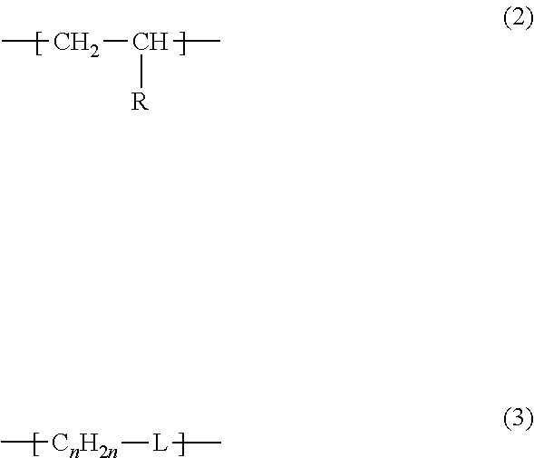
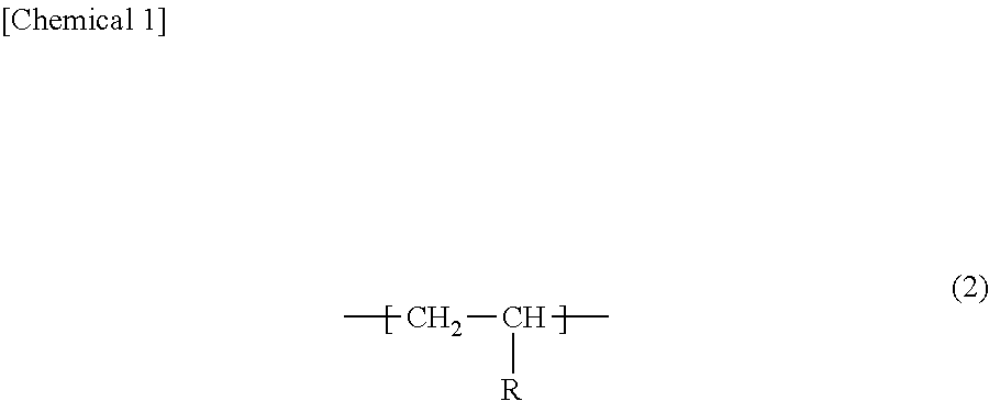
Provided is a secondary battery separator that is lightweight and excels in heat resistance. The secondary battery separator of the present invention includes a porous base layer (A), and a heat resistant layer (B) formed from a non-woven fabric containing a binder and microfibers having a melting point (or a decomposition temperature in case of the microfibers having no melting point) of 200° C. or higher. The microfibers are preferably aramid fibers, and the binder is preferably at least one type selected from a polysaccharide derivative (1), a compound having a constituent unit represented by formula (2), and a compound having a constituent unit represented by Formula (3). In the formulas, R denotes a hydroxyl group, a carboxyl group, a phenyl group, an N-substituted or unsubstituted carbamoyl group, or a 2-oxo-1-pyrrolidinyl group, n is an integer of 2 or higher, and L denotes an ether bond or an (—NH—) group.

Description

TECHNICAL FIELD[0001]The present invention relates to a secondary battery separator, a method for producing a secondary battery separator, and a secondary battery provided with the secondary battery separator. The present application claims the rights of priority of JP 2018-32520 filed in Japan on 26 Feb. 2018, and of JP 2018-134374 filed in Japan on 17 Jul. 2018, the contents of which are incorporated herein.BACKGROUND ART[0002]Separators that insulate a cathode and an anode while retaining an electrolytic solution are used in electricity storage devices such as lithium-ion secondary batteries. Therefore, the separator must ensure electrical insulation properties. In addition, a lithium-ion battery functions by the movement and passage of lithium ions through this separator, and therefore permeability also needs to be ensured.[0003]Furthermore, a lithium-ion secondary battery must also have a “shutdown function” to safely stop the function of the battery by plugging the holes of th...

Claims


Application Information

Patent Timeline
Patent Type & Authority Applications(United States)
IPC IPC(8): H01M2/16H01M2/14H01M50/403H01M50/417H01M50/423H01M50/429H01M50/454H01M50/489
CPCH01M2/162H01M2/145H01M2/1686H01M2/1666H01M2/1653Y02E60/10H01M50/44H01M50/423H01M50/429H01M50/403H01M50/417H01M50/454H01M50/489H01M50/449H01M50/491H01M50/463H01M10/0525Y02P70/50
Inventor YAMAMOTO, AKITOIWAYA, MASAO
Owner DAICEL CHEM IND LTD
Learn More