
Training of photonic reservoir computing systems

a technology of computing system and photonic reservoir, which is applied in computing models, biological models, instruments, etc., can solve the problems of limiting the size of the reservoir, limiting the speed and power efficiency, and simulating large reservoirs or extensive input sequences is both time-consuming and very power-consuming, so as to achieve good classification performance, large topological freedom, and good speed

Active Publication Date: 2020-12-31
UNIV GENT +1
View PDF1 Cites 0 Cited by
  • Summary
  • Abstract
  • Description
  • Claims
  • Application Information

AI Technical Summary

Benefits of technology

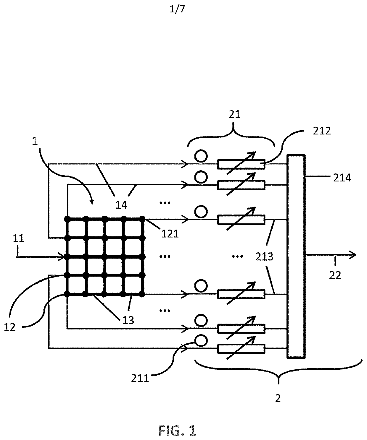
[0006]It is an object of embodiments of the present invention to provide efficient photonic reservoir computing methods and systems with a fully optical readout.
[0007]It is an advantage of embodiments of the present invention that the systems allow for upscaling to a large number of nodes, since the highly efficient processing can be obtained.
[0008]It is an advantage of embodiments according to the present invention that use can be made of training method that does not require exact knowledge of the system states, but is able to reconstruct them in an efficient way by using a particular training sample multiple times.

Problems solved by technology

The sequential character of this workflow sets a limit to the speed and power efficiency: simulating large reservoirs or extensive input sequences is both time intensive and very power consuming.
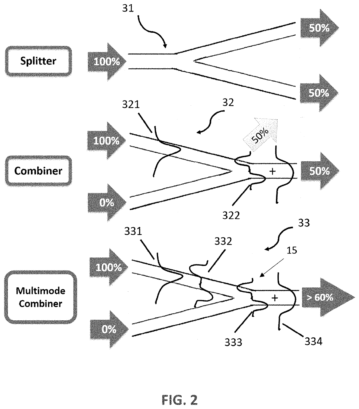
Unfortunately, these components introduce severe losses in the reservoir that set a limit to the size of the reservoir (i.e. the number of neurons).
The larger the network, the more of these combiners are encountered, which means that the information decays rapidly and is not able to reach the other end of the network.
Because the complexity of tasks the reservoir can perform depends on the number of neurons it consists of, these losses also limit the complexity of tasks that can be performed, and consequently there is still room for improvement.

Method used


Image

  • Training of photonic reservoir computing systems
  • Training of photonic reservoir computing systems
  • Training of photonic reservoir computing systems

Examples


Embodiment Construction

[0062]The present invention will be described with respect to particular embodiments and with reference to certain drawings but the invention is not limited thereto but only by the claims. The drawings described are only schematic and are non-limiting. In the drawings, the size of some of the elements may be exaggerated and not drawn on scale for illustrative purposes. The dimensions and the relative dimensions do not correspond to actual reductions to practice of the invention.

[0063]Furthermore, the terms first, second and the like in the description and in the claims, are used for distinguishing between similar elements and not necessarily for describing a sequence, either temporally, spatially, in ranking or in any other manner. It is to be understood that the terms so used are interchangeable under appropriate circumstances and that the embodiments of the invention described herein are capable of operation in other sequences than described or illustrated herein.

[0064]Moreover, t...


PUM


Abstract

A photonics reservoir computing system is described. The system is configured for propagating at least one optical signal so as to create resulting radiation signals in the output channels. The photonics reservoir computing system further comprises weighting elements for weighting signals from the output channels, and at least one optical detector for optically detecting signals from the output channels. The system is adapted for estimating signals from the output channels through an output of the optical detector.

Description

FIELD OF THE INVENTION[0001]The invention relates to the field of optical reservoir computing. More specifically it relates to methods and systems for training and using optical photonic reservoir computing systems with optical readout.BACKGROUND OF THE INVENTION[0002]The field of machine learning aims to teach computer systems how to perform complex tasks on previously unseen data, without explicitly programming them. Examples of such tasks are classification, regression or pattern recognition. The arsenal of available machine learning techniques is comprehensive.[0003]For every application the most appropriate technique has to be selected, depending on the application's specific demands. One important class of techniques are the so-called artificial neural networks, that consist of a network of interconnected neurons. This idea was based on the structure of the human brain and how it processes information. One subclass of the neural networks, called recurrent neural networks (RNN)...

Claims


Application Information

Patent Timeline
Patent Type & Authority Applications(United States)
IPC IPC(8): G06N5/04G06N20/00
CPCG06N5/04G06N20/00G06N3/0675G06N3/044G02F3/028G02B6/125G02B6/1228
Inventor BIENSTMAN, PETERKATUMBA, ANDREWHEYVAERT, JELLEDAMBRE, JONIFREIBERGER, MATTHIAS
Owner UNIV GENT
Learn More