Heat-of-compression recycle system, and sub-systems thereof

a recycling system and heat-of-compression technology, applied in steam engine plants, lighting and heating apparatus, ac network load balancing, etc., can solve the problem of requiring more energy input or was

Pending Publication Date: 2020-12-24
HIGHVIEW ENTERPRISES LTD
View PDF0 Cites 3 Cited by
  • Summary
  • Abstract
  • Description
  • Claims
  • Application Information

AI Technical Summary

Benefits of technology

[0061]It is advantageous to be able to adjust the amount of hot thermal energy provided during pre-stage heating to maximise the work output of the expansion stages for a given grade of hot thermal energy delivered by a thermal energy storage device. This can be achieved by further heating or cooling the first heat transfer fluid, however, this either requires more energy input or wastes stored heat of compression by removing it via cooling. The first aspect of the invention provides an efficient way to achieve hot thermal energy adjustment between expansion stages through the arrangements of conduits.
[0179]Storing the heats of compression from the main air compressor and the recycle air compressor in this way avoids loss of hot thermal energy grade by mixing. Mixing would also lead to the resulting stored temperature being somewhere between the higher main air compressor and lower recycle air compressor temperatures. This may be inefficient to store in either of the thermal energy storage devices described above.

Problems solved by technology

This can be achieved by further heating or cooling the first heat transfer fluid, however, this either requires more energy input or wastes stored heat of compression by removing it via cooling.

Method used


Image

  • Heat-of-compression recycle system, and sub-systems thereof
  • Heat-of-compression recycle system, and sub-systems thereof
  • Heat-of-compression recycle system, and sub-systems thereof

Examples


first embodiment

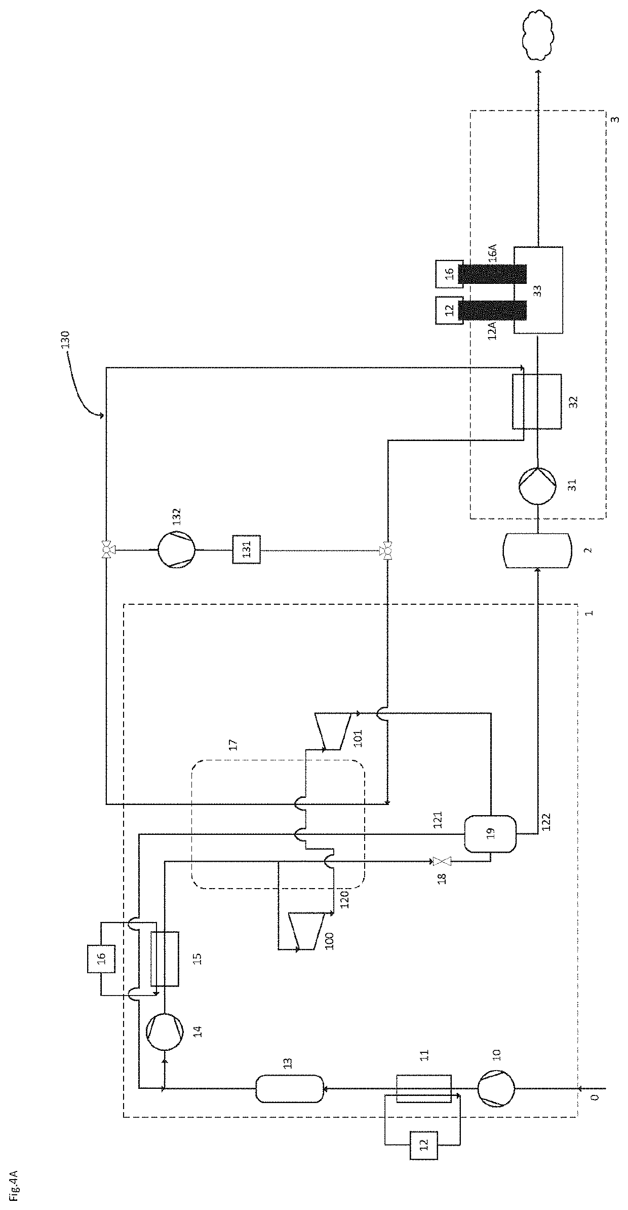
[0200]the invention is depicted in FIG. 4A and is directed to a standalone CES system displaying a liquefaction unit (1), a cryogenic tank (2) and a power recovery unit (3), which exhibits a power island (33) that could adopt any of the configurations depicted in FIG. 5A-5F, each of which is also an embodiment of the present invention. This standalone CES system possesses a heat-of-compression recycle device (11, 12, 15, 16, 12A, 16A) and a first separate closed double loop (130) which transfers the cold thermal energy embedded in the cryogen to the process stream of the liquefaction unit. The hot thermal energy provided to the working fluid of the power recovery unit via at least one power recovery heater may stem from the heat-of-compression recycle device through the second (11, 12, 12A) and third (15, 16, 16A) separate closed double loops. Although it is a standalone system, it is possible to have this embodiment using not only the hot thermal energy provided by the heat-of-comp...

second embodiment

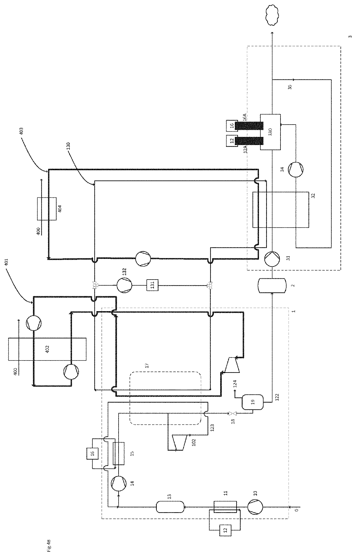
[0220]the invention is depicted in FIG. 4B and is directed to a thermally-integrated system displaying a liquefaction unit (1), a cryogenic tank (2) and a power recovery unit (3) which exhibits a power island (330) that could adopt any of the configurations depicted in FIG. 6A-6F, each of which is also an embodiment of the present invention. This thermally-integrated CES system possesses a heat-of-compression recycle device (11, 12, 15, 16, 12A, 16A) and a first separate closed double loop (130) which transfers the cold thermal energy embedded in the cryogen to the process stream of the liquefaction unit. This CES system receives some waste cold thermal energy from a LNG regasification terminal external to and co-located with said CES system via a first (401) and a second (403) separate closed single loops. The waste cold thermal energy provided by the LNG regasification terminal does not fulfil entirely the needs of the liquefaction unit, which still requires the presence of the fi...


PUM


Abstract

Power recovery sub-systems, cryogenic energy storage systems, and methods of capturing, storing, and re-using thermal energy are disclosed.

Description

FIELD OF THE INVENTION[0001]The present invention relates to power recovery sub-systems and cryogenic energy storage systems with liquefaction and power recovery sub-systems, and particularly to systems and methods for capturing, storing and re-using hot thermal energy.BACKGROUND OF THE INVENTION[0002]Electricity transmission and distribution networks (or grids) must balance the generation of electricity with the demand from consumers. This is normally achieved by modulating the generation side (supply side) by turning power stations on and off, and running some at reduced load. As most existing thermal and nuclear power stations are most efficient when run continuously at full load, there is an efficiency penalty in balancing the supply side in this way. The expected introduction of significant intermittent renewable generation capacity, such as wind turbines and solar collectors, to the networks will further complicate the balancing of the grids, by creating uncertainty in the ava...

Claims


Application Information

Patent Timeline
Patent Type & Authority Applications(United States)
IPC IPC(8): F25J1/02F25J1/00
CPCF25J2210/62F25J1/0202F25J2270/06F25J1/005F25J1/0037F25J2230/30F25J1/0224F25J1/0242H02J3/28H02J15/00F02C6/16F25J1/0012F25J1/004F25J1/0045F25J1/0251F25J1/0268F25J1/0292F25J2205/24F25J2260/30F25J2270/904F01K25/10Y02E60/16
Inventor CASTELLUCCI, NICOLACOCHRANE, COLM JOHN
Owner HIGHVIEW ENTERPRISES LTD
Why Eureka
Try Eureka