
Dielectric reflectarray antenna and method for making the same

Active Publication Date: 2020-12-17
CITY UNIVERSITY OF HONG KONG
View PDF0 Cites 1 Cited by
  • Summary
  • Abstract
  • Description
  • Claims
  • Application Information

AI Technical Summary

Benefits of technology

This patent is about an improved type of antenna that overcomes some of its limitations. The method described in the patent allows for the antenna to be made easily and inexpensively. It can be used for millimeter-wave operations and has a high gain. This makes it useful for applications such as satellite communication, radar detection, and military and defense applications. The method also avoids the need for separate pieces of the antenna, which can save time and reduce costs.

Problems solved by technology

However, microstrip antennas suffered from surface-wave, ohmic-loss, and narrow bandwidths especially at millimeter wave frequencies.
Dielectric reflectarray antenna arranged for operation at the millimeter-wave band, however, is small and difficult to make.
Specifically, the dielectric reflector elements of the array are small and hence difficult to be fixed or mounted accurately (misalignment affects performance).
Problematically, however, the dielectric constants (or relative permittivities) of materials suitable for use in 3D printing are usually low, and the use of material with low dielectric constants would undesirably lead to large antenna size and low antenna gain.

Method used


Image

  • Dielectric reflectarray antenna and method for making the same
  • Dielectric reflectarray antenna and method for making the same
  • Dielectric reflectarray antenna and method for making the same

Examples


Embodiment Construction

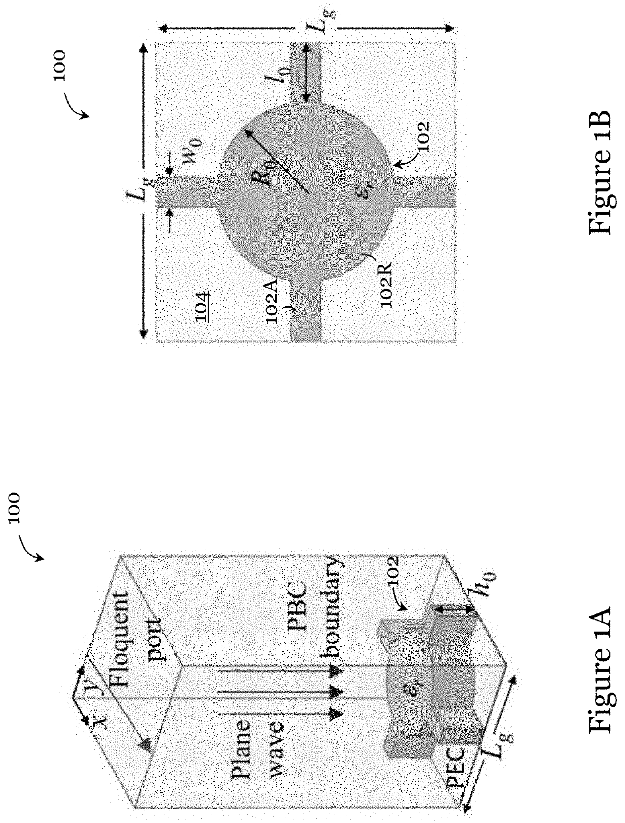
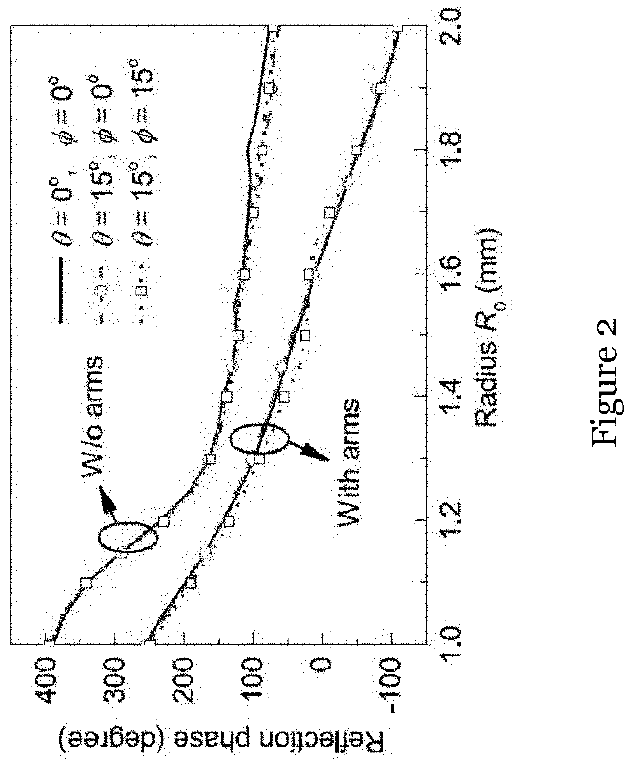
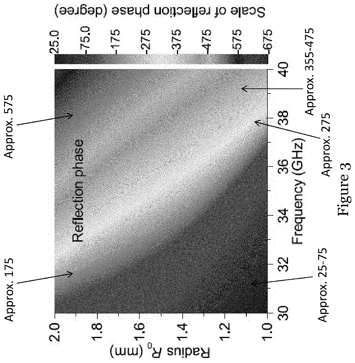
[0051]Referring to FIGS. 1A and 1B, there is shown an illustration of a unit cell 100 of an array in a dielectric reflectarray antenna in one embodiment of the invention. In this embodiment, the unit cell 100 was designed with ANSYS HFSS (a 3D electromagnetic simulation software for designing and simulating high-frequency electronic products) to obtain the required reflection phase response. A Floquet model was used with the periodic boundary condition provided by HFSS. In this example, the size and reflection amplitude of the unit cell 100 are assumed to be the same as or similar to those of the adjacent unit cells in the array. In the example, the size variations of the adjacent elements are assumed to be small.

[0052]As shown in FIGS. 1A and 1B, the unit cell 100 is a “square unit cell” (in plan view, squared contour) that includes a dielectric reflector 102 (also a resonator) element arranged on a conductor ground plane 104. In this example, the dielectric reflector element 102 h...


PUM


Abstract

The invention relates to a method for making a dielectric reflectarray antenna, and a dielectric reflectarray antenna made using such method. The method includes removing, from a substrate having a dielectric layer and a first outer metallic layer arranged on one side of the dielectric layer, the first outer metallic layer to form an intermediate substrate. The method also includes cutting the intermediate substrate to integrally form a dielectric reflectarray with an array of dielectric reflector elements of the dielectric reflectarray antenna.

Description

TECHNICAL FIELD[0001]The invention relates to a method for making a dielectric reflectarray antenna, and a dielectric reflectarray antenna made using such method.BACKGROUND[0002]High-gain antennas are generally used in satellite communications, radar detection, remote sensing, military and defense, etc.[0003]Reflectarray antenna, a combination of reflectors and arrays, is one type of high-gain antenna. The basic configuration of a reflectarray antenna includes a feed source and an array of reflecting elements. Each of the reflecting elements has a respective predetermined phase to collimate or shape the incident high-gain wave-front or beam in the desired direction. The phase shifts provided by the reflecting elements in the array lattice can compensate for the differential spatial phase delays from the feed source and form a planar (or shaped) phase wave-front on the reflectarray aperture. By varying the size or configuration of the reflecting elements, different compensations can ...

Claims


Application Information

Patent Timeline
IPC IPC(8): H01Q19/10H01Q15/14
CPCH01Q15/141H01Q19/10H01Q3/46H01Q21/0087H01P11/001
Inventor LEUNG, KWOK WASUN, YUXIANG
Owner CITY UNIVERSITY OF HONG KONG
Learn More