
Heat exchanger

a technology of heat exchanger and heat exchanger layer, which is applied in the direction of indirect heat exchanger, light and heating apparatus, laminated elements, etc., can solve the problems of non-uniform flow rate of heating medium distributed to the heating medium layer, thick tubes, and inability to secure a wide heat transmission area, so as to achieve effective distribution, simplify heating medium differential distribution unit, and improve heat transmittance efficiency

Inactive Publication Date: 2020-12-10
KYUNGDONG NAVIEN
View PDF0 Cites 1 Cited by
  • Summary
  • Abstract
  • Description
  • Claims
  • Application Information

AI Technical Summary

Benefits of technology

The present invention provides a heat exchanger with a heating medium differential distribution unit to prevent boiling and lime precipitation, improve heat transmittance efficiency, and simplify the structure of the heat exchanger. An extension pipe portion can be added to effectively distribute the heating medium at different flow rates. The heat exchanger can be stacked with a plurality of heat exchange units to increase the capacity without reducing the pressure of the heating medium. The plates are integrally formed to decrease the number of components and simplify the production process. The technical effects of the heat exchanger include improved heat transfer, simplified structure, and increased capacity without increasing pressure.

Problems solved by technology

The heat exchanger according to the related art has problems in that, since a tube is molded to have a flat shape, the tube is deformed to a round shape in a case in which a pressure is applied to a heat transmission medium unit and, since the tube is manufactured to be rolled upward, the tube is thick.
In addition, since the conventional heat exchanger has a structure in which the heat exchanger pipe is wound around a combustion chamber in the coil shape, heat exchange between combustion gas and a heating medium is performed only at a local space adjacent to the heat exchanger, and thus there is a disadvantage in that a wide heat transmission area cannot be secured.
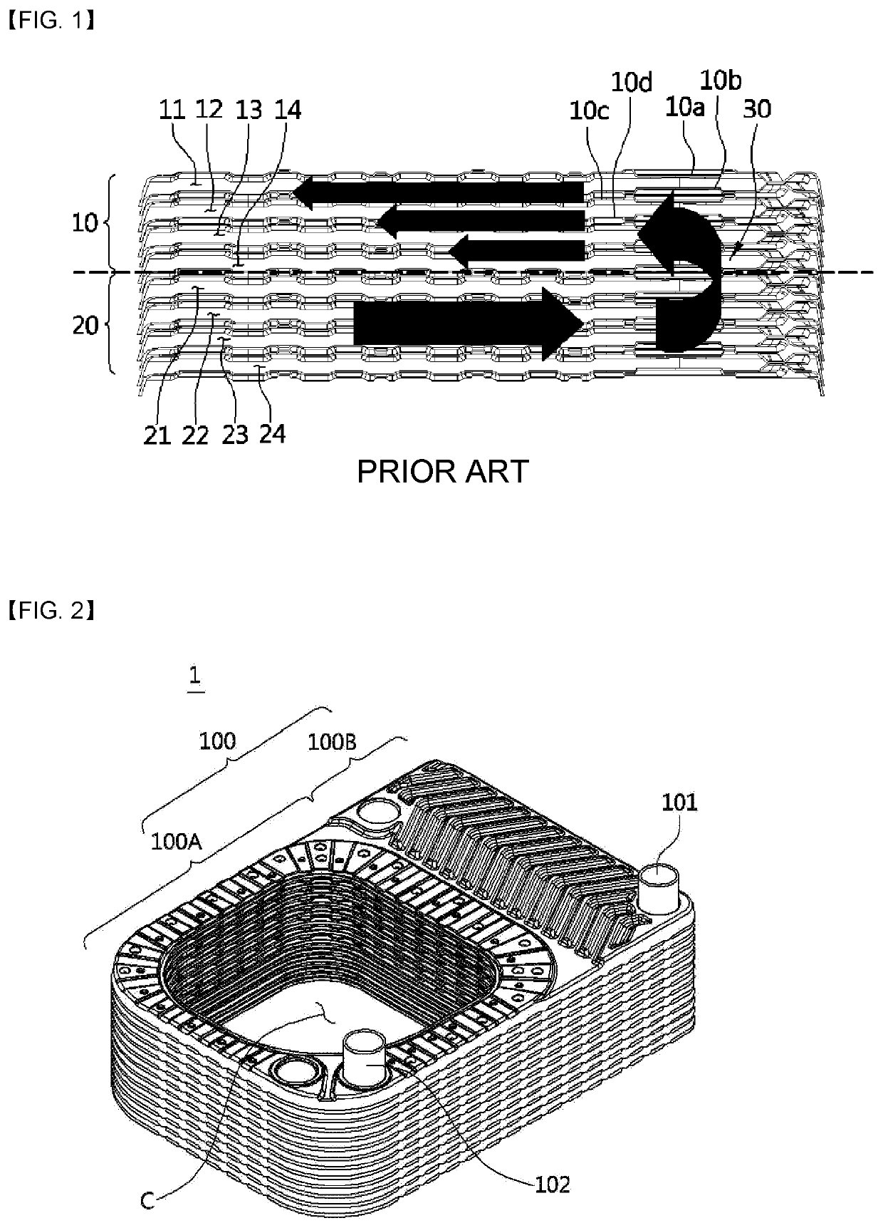
In the case of a plate type heat exchanger disclosed in a document of the related art, a flow direction of a heating medium is changed from a horizontal direction to a vertical direction in a process in which the heating medium is distributed to heating medium flow paths formed as a plurality of layers, and flow rates of the heating medium distributed to the layers of the heating medium flow paths may be non-uniform due to inertia and pressure of the heating medium.
In a case in which the flow rates of the heating medium in the heating medium flow paths of layers are not balanced with the amounts of absorbed heat transmitted to the heating medium through plates, since heat exchange performance between the heating medium and the combustion gas is degraded and, since the heating medium boils in a region in which the flow rate of the heating medium is low due to local overheating, there are problems in that noise is generated and a foreign material such as lime is precipitated.

Method used


Image

  • Heat exchanger
  • Heat exchanger
  • Heat exchanger

Examples


Embodiment Construction

[0082]Hereinafter, configurations and operations related to exemplary embodiments of the present invention will be described below in detail with reference to the accompanying drawings.

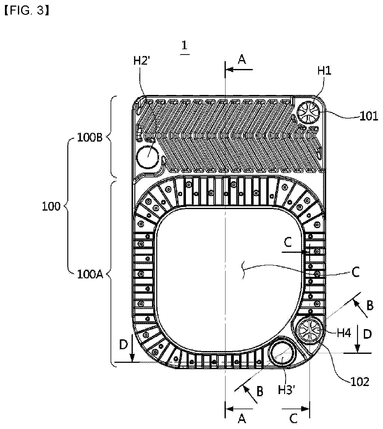
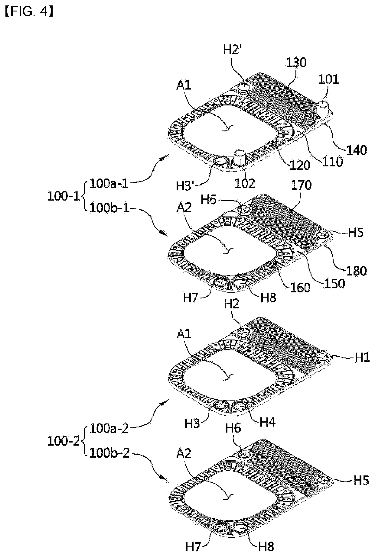
[0083]Referring to FIGS. 2 to 7, a heat exchanger 1 according to one embodiment of the present invention includes a heat exchange unit 100 formed of a plurality of plates stacked around a combustion chamber C in which combustion heat and combustion gas are generated due to combustion of the burner (not shown).

[0084]The heat exchange unit 100 includes a sensible heat exchange unit 100A surrounding an outer side of the combustion chamber C and including one side regions of the plates to heat a heating medium using sensible heat of the combustion gas generated by combustion of the burner and a latent heat exchange unit 100B including the other side regions of the plates to heat the heating medium using latent heat generated while water vapor included in the combustion gas, of which heat is exchanged in t...


PUM


Abstract

The purpose of the present invention is to provide a heat exchanger capable of suppressing boiling and lime precipitation due to local overheating of a heating medium and at the same time improving heat transmittance efficiency. The heat exchanger of the present invention for achieving said purpose comprises: heating medium flow paths, through which a heating medium flows, inside a plurality of laminated plates; and a heat exchange unit in which combustion gas flow paths, through which a combustion gas flows, are alternately formed to be adjacent to each other, wherein the heat exchange units have a heating medium differential distribution unit which enables the flow rate of the heating medium to be differentially distributed to parallel heating medium flow paths of the heat exchange unit such that the flow rate of the heating medium passing through the parallel heating medium flow paths is balanced with the quantity of absorbed heat transmitted to the plates.

Description

TECHNICAL FIELD[0001]The present invention relates to a heat exchanger, and more specifically, to a heat exchanger which allows boiling of a heating medium and lime precipitation from the heating medium to be suppressed and also allows heat transmittance efficiency to be improved by distributing the heating medium at different flow rates such that the flow rates of the heating medium passing through heating medium flow paths formed as a plurality of layers between a plurality of plates are balanced with amounts of absorbed heat.BACKGROUND ART[0002]Boilers for heating or for hot water are apparatuses configured to heat heating water or direct water (hereinafter, referred to as a “heating medium”) using heat sources so as to heat desired places or supply hot water to the places, and include burners configured to burn mixtures of gas and air and heat exchangers configured to transmit combustion heat of combustion gas to the heating medium.[0003]As an example of a conventional heat exch...

Claims


Application Information

Patent Timeline
Patent Type & Authority Applications(United States)
IPC IPC(8): F24H1/12F28F19/00F28F3/08F24H1/00F24H8/00F24H9/00F24H9/02F24H9/12
CPCF24H9/128F24H1/124F24H9/0047F24H1/0027F28F3/086F24H8/00F28F19/00F24H9/02F28D9/0037F28D9/0056F28D20/021F28D2021/0024F28F9/026F28F13/08F28D9/0093Y02B30/00F24H9/45F28D1/0316F28D9/0031F28F9/0273F28F2009/222F24H9/139
Inventor JEONG, IN CHULPARK, JUN GIL
Owner KYUNGDONG NAVIEN
Learn More