Method of determining the evaluation time for a diagnosis

a diagnostic and evaluation time technology, applied in the field of determining the evaluation time for a diagnosis, can solve the problems of undeveloped corresponding monitoring criteria and difficult to determine the appropriate evaluation time, and achieve the effect of low cos

Active Publication Date: 2020-11-19
ROBERT BOSCH GMBH
View PDF0 Cites 0 Cited by
  • Summary
  • Abstract
  • Description
  • Claims
  • Application Information

AI Technical Summary

Benefits of technology

[0007]According to the invention, at least one measured sensor value in a diagnosis method is replaced by a calculated model value that models the component to be diagnosed in the state that is to be reliably recognized. Subsequently, the diagnosis method is executed as a simulation with the calculated model value. A result value from the diagnosis, for example a manipulated variable, an integral or an average that is typically evaluated in the diagnosis, is then checked and the simulated method is conducted until the result value attains a given threshold value. The suitable evaluation time for the diagnosis method is then fixed as the time at which the result value attains the threshold value. It should be pointed out that time and duration are equivalent here. By determining a time, a duration (up to that time) is at the same time also determined. The suitable evaluation period for the diagnosis method is then fixed as the duration after which the result value has attained the threshold value. In this way, the diagnosis evaluation can be optimized in relation to frequency and discrimination of the diagnosis, so as also to result in more accurate diagnoses.
[0011]In a further embodiment, the diagnosis method in an SCR catalyst may comprise the following steps: calculating at least one modeled comparative value for a given state of a model catalyst; detecting at least one measured sensor value in the exhaust gas beyond the catalyst; forming a difference value from the at least one measured sensor value and the at least one modeled comparative value, amplifying the difference value by means of a state observer; forming an integrated value from the integral of multiple difference values over a predetermined period of time to obtain a result value; and feeding the result value back into the model of the model catalyst to correct the modeled comparative value. By means of the observer utilized in this method, it is possible to better adapt the model to the measurement values in the diagnosis. By a method according to the present invention, it is then possible to determine the optimal duration for obtaining diagnosis results that are robust by virtue of a sufficiently corrected model. It will be apparent that the forming of an integrated value will in practice be implemented as a summation.
[0014]The implementation of a method of the invention in the form of a computer program or computer program product with program code for performance of all method steps is also advantageous since this incurs particularly low costs, especially when a control device executing the method is also utilized for further functions and is therefore present in any case. Suitable data carriers for provision of the computer program are especially magnetic, optical and electrical storage means, for example hard drives, flash drives, EEPROMs, DVDs and the like. It is also possible to download a program via computer networks (internet, intranet etc.).

Problems solved by technology

In such methods, however, the problem is that the suitable evaluation time is difficult to determine.
If the diagnosis is evaluated too early, the corresponding monitoring criterion has possibly not yet developed sufficiently, i.e. has not yet been taught in.

Method used


Image

  • Method of determining the evaluation time for a diagnosis
  • Method of determining the evaluation time for a diagnosis
  • Method of determining the evaluation time for a diagnosis

Examples


Embodiment Construction

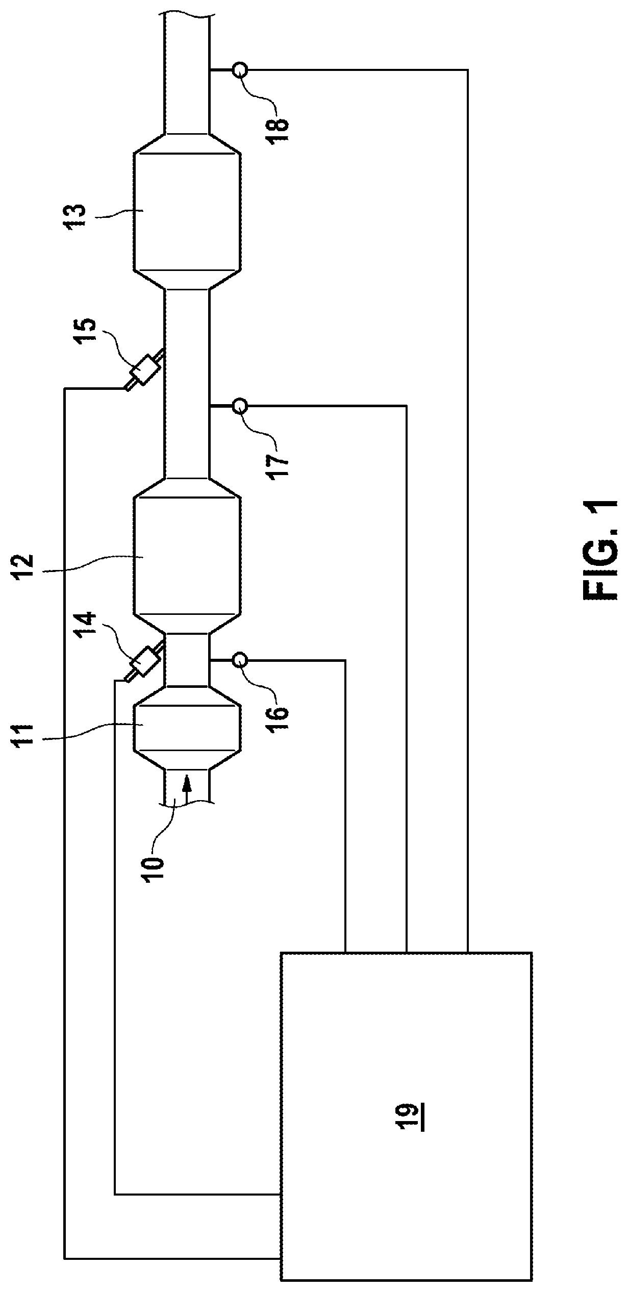
[0021]Embodiments of the invention are especially suitable for diagnosis methods that are to proceed over a particular period of time, and which draw a conclusion as to the state of the component diagnosed, for example a catalyst, on the basis of measured values and model values in combination. Embodiments of the invention are preferentially suitable for “learning” diagnosis methods, i.e. those in which the relevant monitoring criteria form over a certain time, such that evaluation of the diagnosis is possible or advisable only after a particular period of time.

[0022]A diagnosis method for which the optimal evaluation time is to be found may firstly be considered here, wherein measurements and modeled comparison values are to influence the diagnosis method. On the basis of this diagnosis method, it is then likewise possible to replace the values that are provided as measurements with simulated values. For this purpose, it is possible with preference to utilize a simulation of a comp...


PUM


Abstract

A method of determining a suitable evaluation time for a diagnosis method for the diagnosis of a component, wherein the diagnosis method is based on at least one measured sensor value and at least one modeled comparative value (cOBDsim), wherein the method comprises: replacing, in the diagnosis method, at least one measured sensor value with a calculated model value (cBPU), where the model (20) for the calculation of the model value is a model of the component in a state that is to be recognized by the diagnosis method; executing (102, 104, 106) the diagnosis method with the calculated model value; obtaining a result value (aOBDsim) of the diagnosis method; repeating the preceding steps until the result value attains a defined threshold value; and fixing the suitable evaluation time in the diagnosis method as the time after which the result value has attained the threshold value.

Description

BACKGROUND OF THE INVENTION[0001]The present invention relates to a method of determining a suitable evaluation time for a diagnosis method in a component, and to a computation unit and a computer program for performance thereof.[0002]In motor vehicles, many systems are monitored to ensure correct function and compliance with limits, for example all systems relevant to exhaust gas, especially the catalysts. According to the legislation, strict compliance with different limits, frequently specified as emissions limits, is then necessary.[0003]Since faulty catalysts can no longer achieve adequate conversion of pollutants, for example, the state of an SCR (selective catalytic reduction) catalyst for reduction of nitrogen oxides (NOx) in the exhaust gas in operation is monitored continuously. The nitrogen oxides here include nitrogen monoxide, NO, and nitrogen dioxide, NO2. The basic principle of the SCR catalyst is that nitrogen oxide molecules are reduced at the catalyst surface in th...

Claims


Application Information

Patent Timeline
Patent Type & Authority Applications(United States)
IPC IPC(8): G01M15/10
CPCG01M15/102F01N11/00F01N9/005F01N2560/026F01N2560/021
Inventor BASTOREALA, ARTHURPFISTER, TOBIAS
Owner ROBERT BOSCH GMBH
Why Eureka
Try Eureka