Female element and fluid connection

Active Publication Date: 2020-11-19
STAUBLI FAVERGES SA
View PDF0 Cites 2 Cited by
  • Summary
  • Abstract
  • Description
  • Claims
  • Application Information

AI Technical Summary

Benefits of technology

The invention proposes a new female element that is small and reliable, with easier locking and unlocking. The front of the female element has a small size, while the interior has a large volume. The invention uses a resilient member and a return plunger to transmit the force to the locking elements. This design reduces the number of parts, simplifies production, decreases bulk, and increases resistance to wear. The female element can be unlocked with a smaller force compared to previous designs, reducing wear and tear. The invention also includes a fluid connection to join pressurized fluid lines, consisting of a female element and a male element. The male element is designed to be easily connected and disconnected from the female element, and to prevent the axial removal of the male element.

Problems solved by technology

In general, the connections are connected manually, which may require a substantial installation and uninstallation time.
However, this type of connection may have certain drawbacks in terms of bulk or disconnection manipulation.
However, due to the radial contact and maintenance of the movable ring on the locking elements, the travel of the ring is significant and requires providing a relatively long annular space within the main body of the female endpiece.
As a result, this known female endpiece is relatively bulky in the axial direction and in the radial direction.
However, this known female connection member has many drawbacks.
The individual action of each spring on its respective hollow cylinder makes the locking and unlocking uncertain and potentially physically difficult, inasmuch as each hollow cylinder and / or its respective spring may become jammed in the cylindrical housing in question, by bracing, surface pollution, and / or wearing of the parts.

Method used


Image

  • Female element and fluid connection
  • Female element and fluid connection
  • Female element and fluid connection

Examples


Embodiment Construction

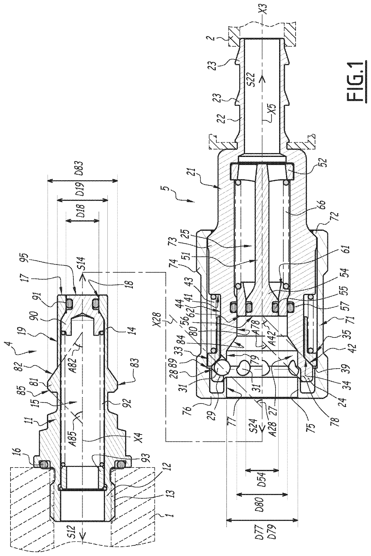
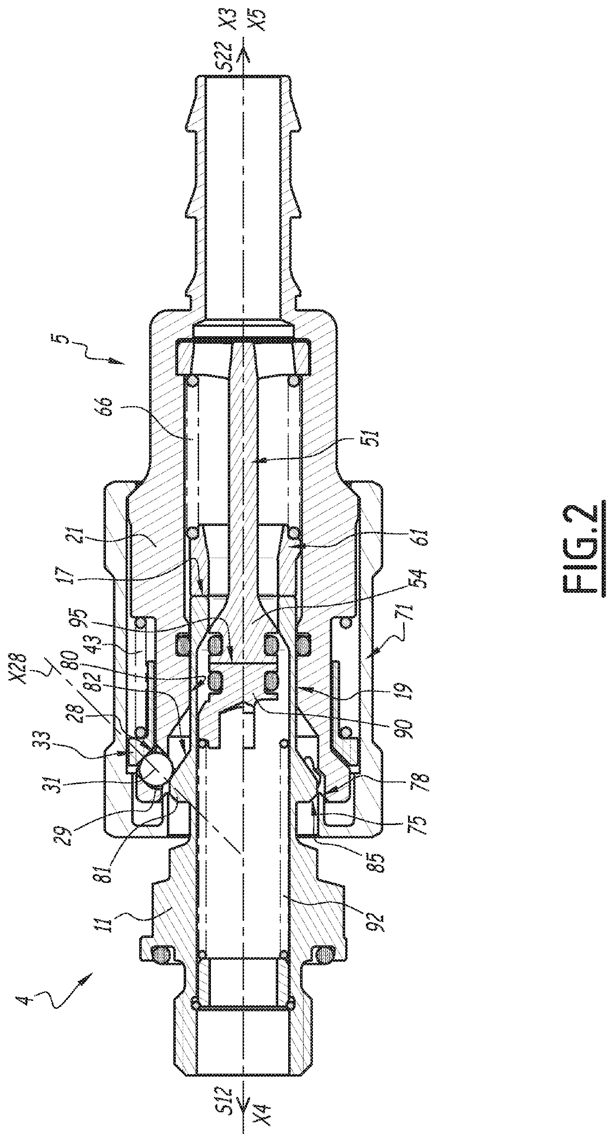
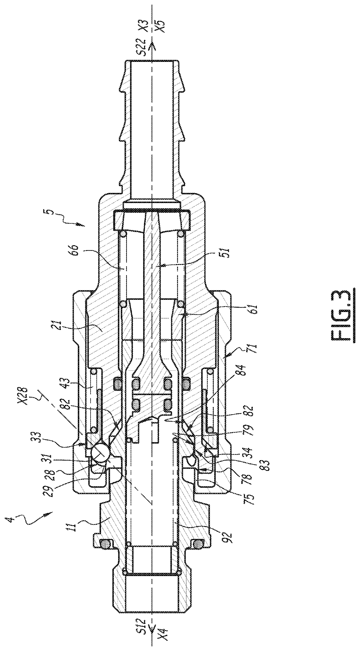
[0058]FIGS. 1 to 6 show a fluid connection according to a first embodiment. The connection is designed to join a pressurized fluid line 1, and a pressurized fluid line 2, shown in broken lines in FIG. 1. The pressurized fluid is for example a heat transfer liquid.

[0059]The fluid connection comprises a male element 4, or male endpiece, and a female element 5, which are complementary and which are both coaxial with the central axis X3 of the connection, when the elements 4 and 5 are in a coupled configuration, as shown in FIG. 4. The male element 4 and the female element 5 each define a respective central axis X4 and X5, which is combined with the central axis X3 when the elements 4 and 5 are in the coupled configuration. In FIG. 1, the elements 4 and 5 are shown in an uncoupled configuration.

[0060]In the coupled configuration, the pressurized fluid delivered by the line 2 circulates within the female element 5, then the male element 4, to be received by the line 1, parallel to the ce...


PUM


Abstract

A female fluid connection element (5), configured to be coupled with a male element (4). A female body (21), which has an insertion channel (27) of the male element (4); locking elements (31) movable between positions; and a maneuvering ring (71) with an inner sleeve (75) for driving the locking element (31) to their proximal position. In order to have a small bulk and to offer particularly easy and reliable locking and unlocking, the female element (5) has a return plunger (33), returning the locking elements (31) toward their distal position, and a resilient member (43), exerting a return force to bring the return plunger (33) back toward a forward position. By being moved toward its withdrawn position, the maneuvering ring (71) drives the return plunger (33) toward a rear position, such that it does not exert a return force on the locking elements (31).

Description

BACKGROUND OF THE INVENTION[0001]The present invention relates to a female element, for a fluid connection designed for joining pressurized fluid lines, as well as a fluid connection comprising such a female element.[0002]The invention in particular relates to the field of quick connections, for connecting heat transfer fluid pipes designed for cooling computer server facilities, or similar electronic or electrotechnical systems.[0003]The connection of a pipe for supplying a computer bay with cooling liquid requires coupling one or several connections, in order to produce circuits and / or loops for distributing the cooling liquid. Each connection is made up of a male element, which is attached on the bay side, and a female element, on the supply side, the male element being coupled to a cooling pipe and the female element being coupled to a supply pipe.[0004]In general, the connections are connected manually, which may require a substantial installation and uninstallation time. Thus,...

Claims


Application Information

Patent Timeline
IPC IPC(8): F16L37/23
CPCF16L37/23F16L37/22F16L37/34F16L37/35
Inventor TIBERGHIEN, ALAIN-CHRISTOPHEDURIEUX, CHRISTOPHEMAYER, ROMAIN
Owner STAUBLI FAVERGES SA
Why Eureka
Try Eureka