
Optical system for narrowing the bandwidth of radiation

a radiation bandwidth and radiation optical technology, applied in optics, lasers, laser details, etc., can solve the problems of inherently low power conversion efficiency of spectral filtering methods, inability to achieve a linear bandwidth compression technique, and difficulty in narrowing the bandwidth of incident radiation beams

Inactive Publication Date: 2020-10-22
VICTORIA LINK LTD
View PDF0 Cites 0 Cited by
  • Summary
  • Abstract
  • Description
  • Claims
  • Application Information

AI Technical Summary

Benefits of technology

The invention uses a thin BBO crystal to achieve broad tuning for SFG, which allows for the matching of input wavelengths across a wide spectrum. By rotating the crystal and mirrors, different SFG signal wavelengths can be generated, resulting in narrowband pulses with high quality. The technical effect of the invention is the improved performance and reliability of SFG systems for various applications such as optical communication and sensing.

Problems solved by technology

The conversion of femtosecond broadband laser pulses to picosecond narrowband pulses presents challenges because achievable bandwidth compression is typically a trade-off between efficiency and experimental simplicity.
While broadly tunable and relatively experimentally simplistic in design, spectral filtering methods suffer from inherently low power conversion efficiency due to the inversely proportional nature of narrow-bandwidth selection and power throughput, with typical energy losses of the fundamental femtosecond source of about 99.8% to generate picosecond pulses that are sufficiently spectrally narrow.
While improving power conversion efficiency, to date nonlinear bandwidth compression techniques remain experimentally complex in nature, require expensive optical dispersion components that typically have a large physical footprint and are challenging to tune and optimise.

Method used


Image

  • Optical system for narrowing the bandwidth of radiation
  • Optical system for narrowing the bandwidth of radiation
  • Optical system for narrowing the bandwidth of radiation

Examples


first embodiment

Bandwidth Compressor—First Embodiment

[0062]The principle of bandwidth narrowing will first be described in broad, functional terms before specific configurations of bandwidth compressors according to particular embodiments are described.

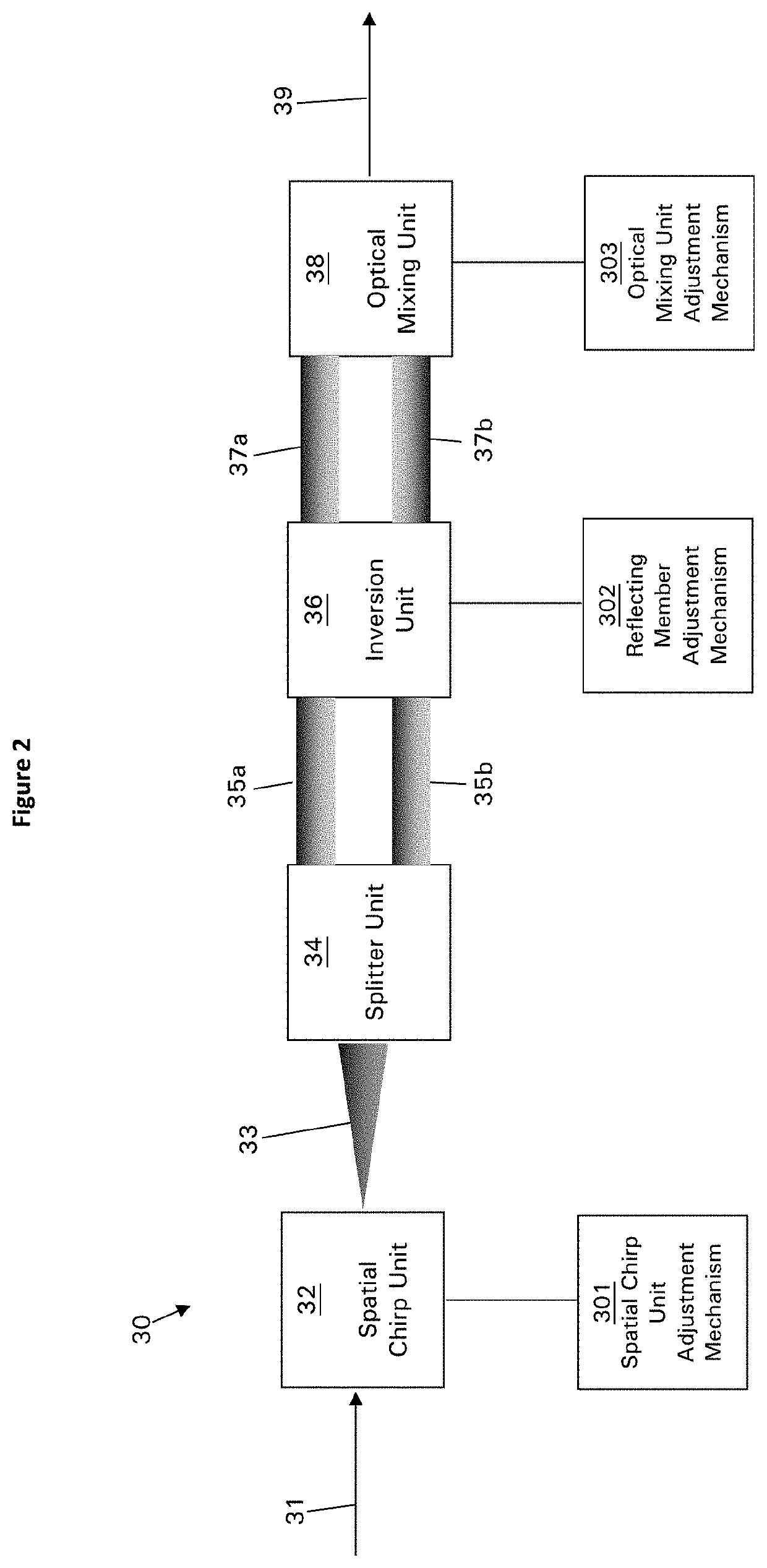
[0063]FIG. 2 is a functional illustration of an optical system 30 for narrowing the bandwidth of a beam of incident radiation, or bandwidth compressor, according to one embodiment of the invention.

[0064]Optical system 30, and optical systems according to other embodiments of the invention, comprises a plurality of units. Each unit may be formed from a single component or member, or each unit may be formed from a plurality of components or members that operate together to perform a function. The components of each unit may be coupled together or they may be separate. Any given component may form part of more than one unit, for example if that component performs or contributes to multiple functions.

[0065]Optical system 30 receives a beam 31, or pulse, ...

second embodiment

Bandwidth Compressor—Second Embodiment

[0078]FIG. 13 is a functional illustration of an optical system 140 for narrowing the bandwidth of a beam of incident radiation, or bandwidth compressor, according to another embodiment of the invention.

[0079]Optical system 140 comprises an optical mixing unit 148 that is configured to mix beams of radiation 147a and 147b to produce output beam 149 in a similar manner to that described above in relation to optical mixing unit 38. Beams 147a and 147b are spatially chirped with beam 147a being inverted relative to beam 147b so that optical mixing unit 148 sum-frequency mixes the beams.

[0080]Beams 147a and 147b may be produced from beams 143a and 143b that are not inverted relative to each other by inversion unit 146a acting on beam 143a to invert the beam relative to beam 143b to produce inverted beam 147a. At the same time, beam 143b may pass through ‘non-inversion’ unit 146b. Non-inversion unit 146b may comprise one or more optical members that ...

third embodiment

Bandwidth Compressor—Third Embodiment

[0083]Particular configurations of bandwidth compression systems according to embodiments of the invention will now be described. It should be understood that, where a component is described in relation to one embodiment, that component may be replaced with another component of equivalent or similar function, for example as described herein in relation to another embodiment of the invention, even if not explicitly stated.

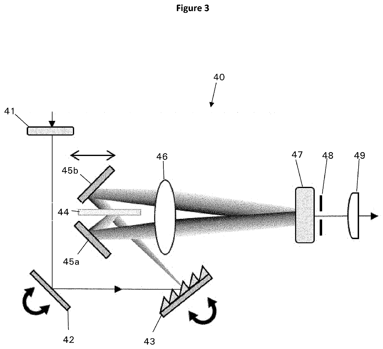
[0084]FIG. 3 is a plan view schematic illustration of an optical system 40 for narrowing the bandwidth of a beam of incident radiation, or bandwidth compressor, according to another embodiment of the invention.

[0085]In optical system 40, the input beam is received by a polariser 41 configured to polarise the input beam. Polariser 41 may comprise a half wave-plate or any other polarising member or assembly of polarising members. The polariser 41 is not present in all embodiments, although where it is present it may improve the eff...


PUM


Abstract

An optical system for narrowing the bandwidth of a beam of incident radiation includes an optical mixing unit configured to receive a first beam of radiation and a second beam of radiation. The first and second beams are spatially chirped and the first beam is inverted relative to the second beam. The optical mixing unit includes an optical mixing member, which includes a nonlinear optical medium to mix the first and second beams into an output beam having a narrower bandwidth than the beam of incident radiation.

Description

FIELD OF INVENTION[0001]The invention relates to optical systems for narrowing the bandwidth of radiation. In some embodiments the invention relates to optical systems for reducing the spectral bandwidth of a laser pulse, for example converting a spectrally broad femtosecond laser pulse into a spectrally narrow picosecond pulse.BACKGROUND TO THE INVENTION[0002]Generation of narrowband laser pulses, for example intense narrowband picosecond laser pulses, is of significant interest in ultrafast laser applications where high spectral resolution is required, such as time-resolved vibrational pump-probe spectroscopy and sum-frequency generation (SFG) surface spectroscopy. The conversion of femtosecond broadband laser pulses to picosecond narrowband pulses presents challenges because achievable bandwidth compression is typically a trade-off between efficiency and experimental simplicity.[0003]Linear methods of bandwidth compression involve the spectral filtering of a femtosecond broadband...

Claims


Application Information

Patent Timeline
IPC IPC(8): G02F1/35H01S3/00G02B27/10G02F1/355G02B27/30
CPCG02F1/3551H01S3/1636H01S3/0092H01S3/0071G02F1/3544G02B27/1086H01S3/1625G02B27/30G02F1/353H01S3/005H01S3/0078G02F1/35H01S3/0057
Inventor PRASAD, SHYAMAL KUSH KANCHANMONAHAN, NICHOLAS RICHARDTHORN, KAREN ELISABETHCHEN, KAIHODGKISS, JUSTIN MARK
Owner VICTORIA LINK LTD
Learn More