
Anatomical silicon models and additive manufacturing thereof

an anatomical model and additive manufacturing technology, applied in the field of additive production of anatomical models, can solve the problems of not providing a realistic reconstruction of treatment situations or surgical situations, unable to manufacture complex anatomical models, and only being able to meet the needs of educational models,

Inactive Publication Date: 2020-10-08
WACKER CHEM GMBH
View PDF2 Cites 6 Cited by
  • Summary
  • Abstract
  • Description
  • Claims
  • Application Information

AI Technical Summary

Benefits of technology

The invention provides a method to make complex anatomical models in a simple and cost-effective way. The models should accurately copy the real tissues or body parts in question in terms of their mechanical and optical properties.

Problems solved by technology

However, what is disadvantageous is that these methods and printing materials are only suitable to a limited extent or are not suitable at all for the production of models for many anatomical structures.
Especially for soft, elastic elements which deform easily under a load, these models do not provide a possibility of reconstructing treatment situations or surgical situations in a realistic manner.
One disadvantage of indirect methods is that the manufacturing of complex anatomical models is not possible or is only possible with very great effort.
Furthermore, all indirect methods have the disadvantage that many individual manufacturing steps are necessary in order to manufacture an anatomical silicone model and that a time-consuming, cost-intensive process with, in some cases, a high proportion of manual work steps is thus concerned.
One disadvantage of this method is the precise placement of tiniest quantities of the silicone printing compound, placement which is not achievable for the printing of fine details.
Furthermore, the time of crosslinking can no longer be influenced after the mixing of the two rubber components, and this has, inter alia, the disadvantage that regions of the silicone rubber composition that vary greatly in degree of crosslinking are contacted in the course of the printing operation (when the processing time of the printing compound is shorter than the printing time) or that the printed structure has no loadability (when the processing time of the printing compound is longer than the printing time).

Method used


Image

  • Anatomical silicon models and additive manufacturing thereof
  • Anatomical silicon models and additive manufacturing thereof
  • Anatomical silicon models and additive manufacturing thereof

Examples


examples

[0109]Small-Child Cleft Lip-and-Palate Model (CLP Model)

[0110]a. Generation of the Digital Model:

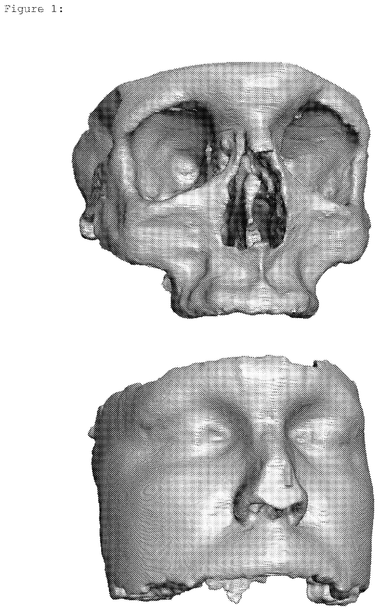
[0111]The starting point is a DICOM data set from an adult in the facial region. Of this, the upper jaw and the adjoining bone regions without the teeth are segmented, as are the surrounding soft material consisting of skin, muscles and other soft-tissue structures in a second model. The segmented models are depicted in FIG. 1.

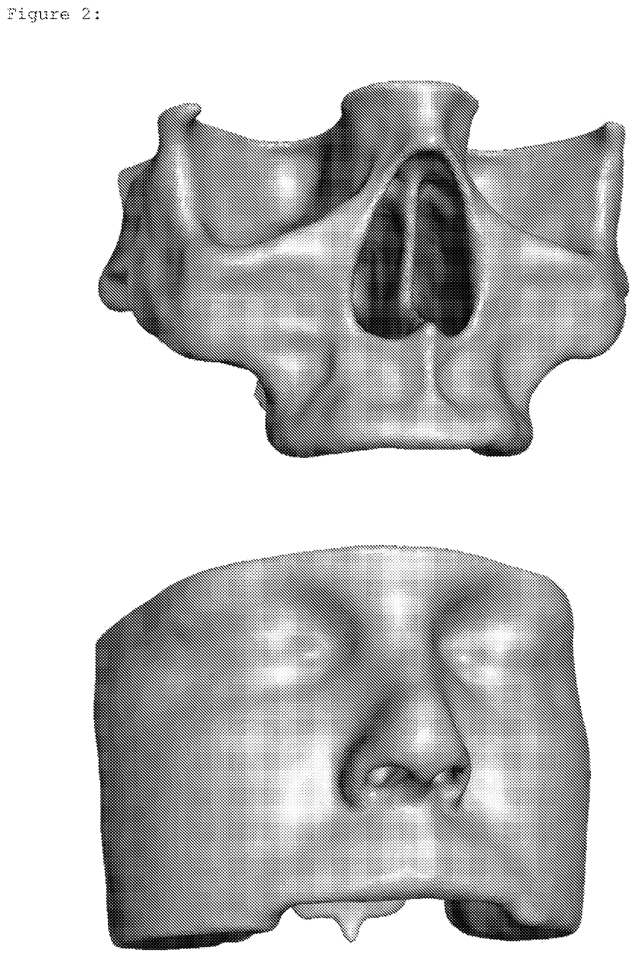
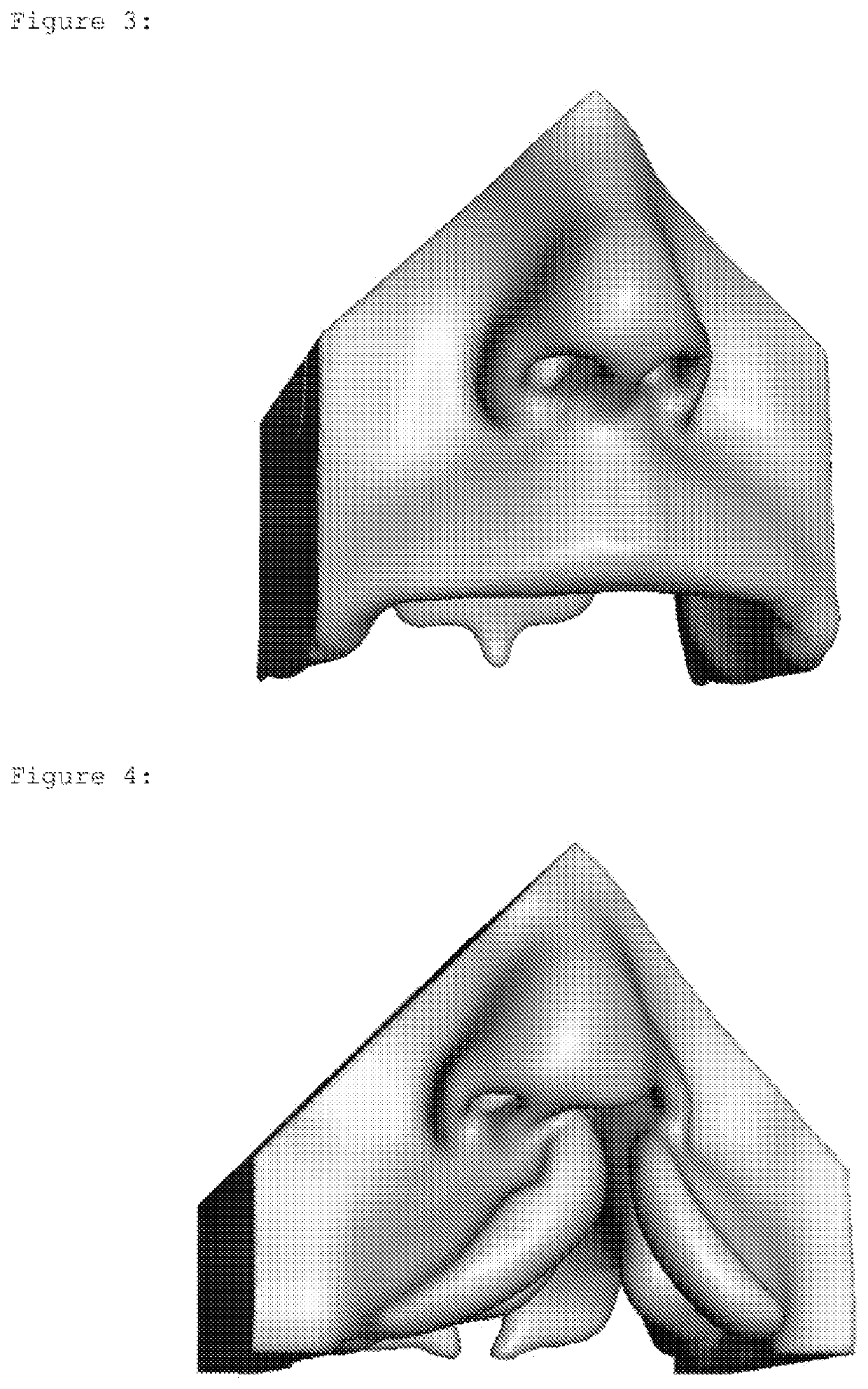
[0112]In the next step, the networks of the segmented models are repaired, holes are filled and the surfaces are smoothed. The bone contours are adjusted to those of an infant. For the soft-tissue model, the nose, nasal septum, lip contour, labial frenulum and, if necessary, further structures are shaped. For easier processing and smoothing of the inner side of the lips and cheeks, the palate is separated in the region of the hard palate. A new palate is created via an offset from the upper jaw of the bone model and is added to the soft-tissue model via Boolean ope...


PUM

PropertyMeasurementUnit
Temperatureaaaaaaaaaa
Viscosityaaaaaaaaaa
Viscosityaaaaaaaaaa

Abstract

Anatomical models are produced by the drop on demand method using at least two structure forming materials which are different from each other, and as a result can accurately mimic either generic or patient specific structures, including, when desired, various colors and hardnesses representing different types of tissue.

Description

CROSS REFERENCE TO RELATED APPLICATIONS[0001]This application is the U.S. National Phase of PCT Appln. No. PCT / EP2017 / 074911, filed Sep. 29, 2017, the disclosure of which is incorporated in its entirety by reference herein.BACKGROUND OF THE INVENTION1. Field of the Invention[0002]The invention relates to a method for the additive production of an anatomical model using a 3D printing device. The method is characterized in that at least one silicone rubber composition crosslinkable by electromagnetic radiation is used as a printing compound. As a result of layer-by-layer application of the printing compounds, the manufacturing of complex anatomies is moreover made possible.[0003]The anatomical models thus generated are particularly realistic and can be of use to skilled medical personnel, for example for training, practicing surgical techniques, illustrating complex clinical pictures or patient-personalized, and preoperative surgical planning. The invention also relates to anatomical ...

Claims


Application Information

Patent Timeline
IPC IPC(8): B29C64/112B29C64/386G09B23/30
CPCB33Y80/00B33Y10/00B33Y50/00G09B23/30B33Y70/00B29C64/112B29C64/386
Inventor SEITZ, VERARIEDLE, HANNAH
Owner WACKER CHEM GMBH
Learn More