
Radome for radar sensor in a motor vehicle, and corresponding radar sensor

Active Publication Date: 2013-07-18
ROBERT BOSCH GMBH
View PDF27 Cites 9 Cited by
  • Summary
  • Abstract
  • Description
  • Claims
  • Application Information

AI Technical Summary

Benefits of technology

The present invention relates to a radar sensor that has a compact radome design, which allows for the arrangement of electromagnetic wave generating and radiating components to be disposed close to each other without interfering with their radiation. The use of high-frequency antennas simplifies the radiating process and reduces costs. The technical effect is a more efficient and compact radar sensor with improved performance and reduced space requirement.

Problems solved by technology

However, because of the required characteristic of allowing radar beams to pass as freely as possible, such radomes require a lot of space.

Method used


Image

  • Radome for radar sensor in a motor vehicle, and corresponding radar sensor
  • Radome for radar sensor in a motor vehicle, and corresponding radar sensor
  • Radome for radar sensor in a motor vehicle, and corresponding radar sensor

Examples


Embodiment Construction

[0019]In the figures, identical or functionally equivalent components are denoted by like reference numerals, provided that nothing is indicated to the contrary.

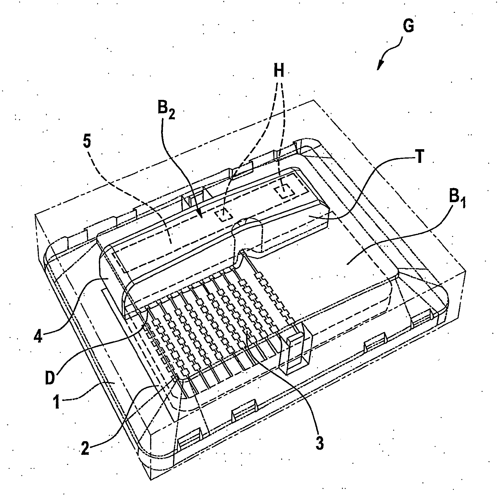
[0020]FIG. 1 shows a radar sensor including a radome according to a first specific embodiment of the present invention, in a perspective view.

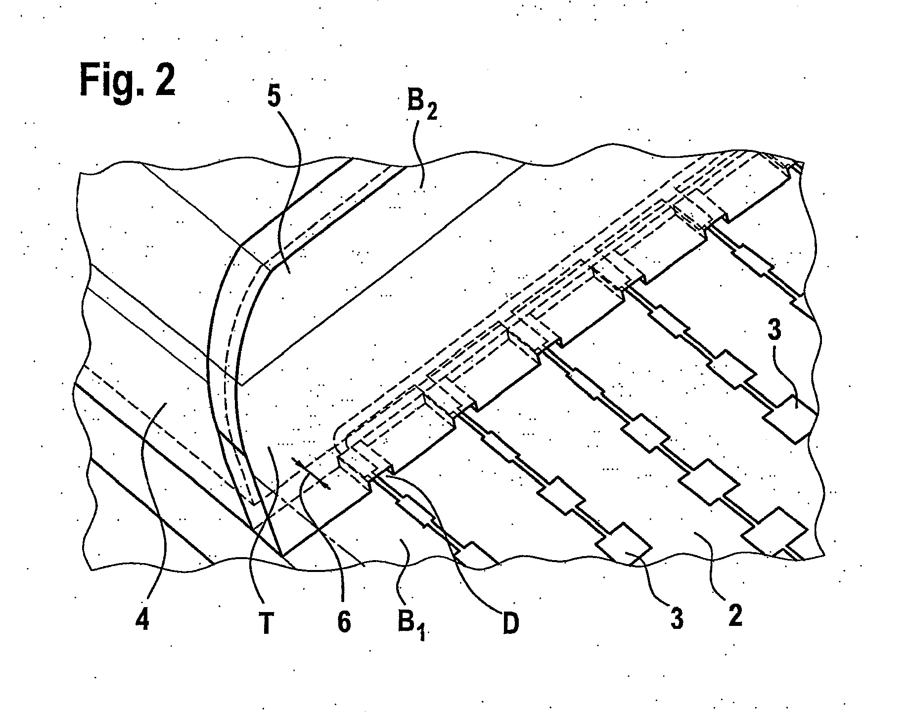
[0021]In FIG. 1, a radar sensor G having a radome 1 is shown in a perspective view. A planar circuit board 2 is disposed inside radar sensor G. Radome 1 includes two regions B1, B2 and subdivides circuit board 2 on its top surface into two regions B1, B2, which are disposed generally next to each other. First region B1 covers approximately ⅔ of the surface of circuit board 2. Second region B2 covers approximately ⅓ of the surface of circuit board 2. A plurality of circuit tracks implemented as high-frequency antennas 3 extend on circuit board 2, parallel to each other. High-frequency antennas 3 extending in parallel also project into second region B2 of radome 1. Second region B2 is co...


PUM


Abstract

A radome for a radar sensor in a motor vehicle. The radome includes a first region, which is permeable to at least one specific type of electromagnetic waves, in particular radar waves, and a second region, which includes a shield, so that the second region is impermeable to the specific type of electromagnetic waves. Also, a radar sensor is described.

Description

FIELD OF THE INVENTION[0001]The present invention relates to a radome for a radar sensor in a motor vehicle and to a corresponding radar sensor.BACKGROUND INFORMATION[0002]The use of driver assistance systems, especially distance warning or distance-keeping systems in motor vehicles is increasing steadily. In the case of distance-keeping systems on the basis of radar sensors, the corresponding radar sensors are covered by radomes.[0003]A radome for a radar sensor in a motor vehicle is described in European Patent No. EP 2 151 888 A1; here, at least one wall is provided with at least one three-dimensional first structure on a first surface, and a second surface that lies across from the first surface has a second structure, which is adapted to the at least one first structure such that the optical path for electromagnetic waves is generally identical at points of the wall provided with a structure and those without structure.[0004]However, because of the required characteristic of al...

Claims


Application Information

Patent Timeline
IPC IPC(8): G01S7/03H01Q1/42G01S13/931
CPCG01S7/032G01S13/931G01S2007/028H01Q1/3233H01Q1/3283G01S2013/9325H01Q1/526H01Q9/0407H01Q21/065H01Q21/08G01S7/03H01Q1/42G01S7/028
Inventor WALDSCHMIDT, CHRISTIANHELLINGER, RAPHAELHANSEN, THOMASBINZER, THOMAS
Owner ROBERT BOSCH GMBH
Learn More