Stabilized horizontal-axis wind turbine

a horizontal-axis wind turbine and stabilizer technology, applied in the direction of machines/engines, mechanical equipment, transportation and packaging, etc., can solve the problems of increasing design complexity, increasing the difficulty of building off-shore wind turbines in the united states, and increasing the cost of construction. , to achieve the effect of economical and compact, cost saving, and weight saving

Active Publication Date: 2020-09-24
SYROVY GEORGE J
View PDF0 Cites 5 Cited by
  • Summary
  • Abstract
  • Description
  • Claims
  • Application Information

AI Technical Summary

Benefits of technology

[0014]Applicant has observed that of all the motions possible for a floating horizontal axis wind turbine—heave, sway, surge, roll, pitch, and yaw—only the yaw and pitch components have a substantial effect on the efficiency of the turbine. He has therefore devised simplified means for controlling those two variables, so as to produce a floating horizontal axis wind turbine that is efficient in cost, weight, and operation. He has also noted that the simplified construction makes possible ways to mount multiple wind turbines in a much more economical and compact way than hitherto possible. The system is substantially independent of the type of flotation system employed. Some aspects of the invention are also applicable to land-based wind turbines.

Problems solved by technology

The blade pitch-control mechanism produces an area of weakness in the blade-hub structure and adds complication to the design.
Wind turbines also require a great deal of clear space—ten rotor diameters in the direction of the wind, and three rotor diameters in every other direction.
Building off-shore wind turbines in the United States is more difficult than in many European locations, where many suitable off-shore locations are in shallow water.
Traditional bottom-mounted supports, as are used in shallow water, are not economical at such depths.
As applied to a horizontal-axis wind turbine, all of these approaches, particularly the first two, require a very large weight as compared with the swept area of the turbine.
Although the approaches previously suggested may be sufficient to keep the structure afloat, they do not provide the kind of stability needed for efficient operation of the turbine.
Any rotational movement of the turbine's mast toward or away from the wind (“pitch”) greatly reduces the efficiency of the turbine.
An angle of attack varying from zero by even two or three degrees greatly reduces the efficiency.
The stability problem of all conventional horizontal axis wind turbines, both on land and particularly off-shore, is exacerbated by the need for yaw positioning motors, frequently eight or more motors, at the top of the mast.
These yaw motors make the turbine even more top-heavy.

Method used


Image

  • Stabilized horizontal-axis wind turbine
  • Stabilized horizontal-axis wind turbine
  • Stabilized horizontal-axis wind turbine

Examples


first embodiment

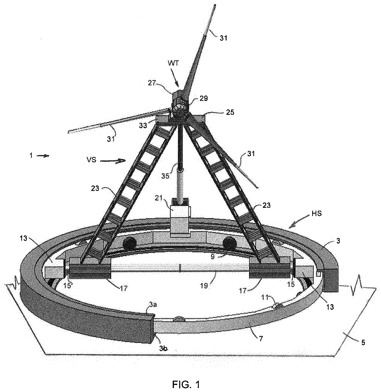
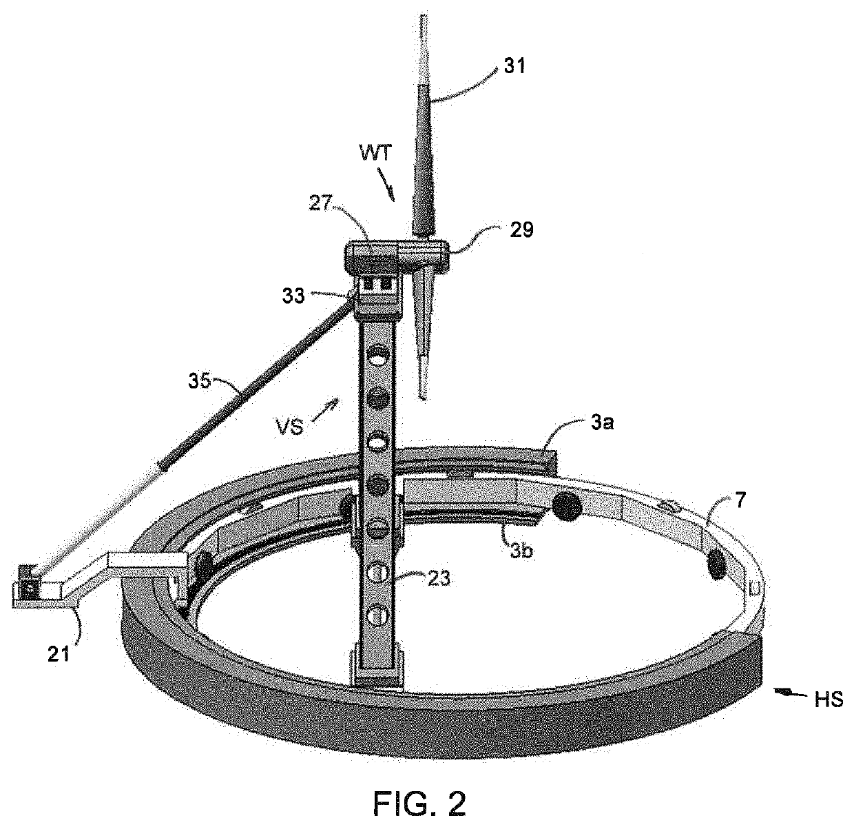
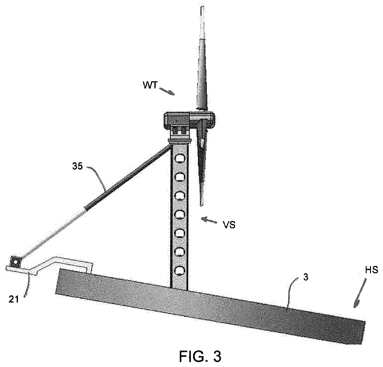
[0057]Another embodiment 101 of the stabilized horizontal-axis wind turbine of the invention is shown in FIGS. 6 and 7. This embodiment differs from the first in replacing the rotatable support 17 for the legs 23 with a fixed support 117 for legs 123 and replacing the adjustable third leg 35 with a fixed leg 135 attached to a cross-brace 139. The fixed leg 135 may be mounted to a boss on the rotatable inner ring 107. In this embodiment, the turbine pedestal 125 is rotatably supported by bearing blocks 141 mounted to upper portions of the legs 123 through stub shafts 143. A rigid extension bar 145 on the back side of the nacelle 127 is connected by a pivot 147 to the upper end of an extendible arm 151. The extendible arm 151 is illustratively a hydraulic cylinder, the lower end of which is connected to the fixed third leg 135 by a pivot 153. Illustratively, the pivot 153 houses a controller for controlling the hydraulic cylinder 151. In other embodiments, the pivot 153 is a pinion mo...

embodiment 201

[0058]FIGS. 8-10 show another embodiment 201 of the invention, having no mechanism to change the pitch of the wind turbine WT. Like the other embodiments, this embodiment is suited to uses in which the horizontal support is fixed against movement. Examples would be on land, in shallow water where the structure may be supported by the sea floor, or on a flat rooftop. Unlike those embodiments, however, it is not suited for use on a floating platform.

[0059]In this embodiment, the generally horizontal support HS″ includes a rotatable inner ring 207 similar to the inner ring 7 of the first embodiment, but with a cross-brace 219. The outer ring is reduced to six “jaws”203. As shown in FIG. 10, each jaw 103 has an upper jaw part 203a and a lower jaw part 203b. The upper jaw part 203a carries horizontal rollers 261 for controlling vertical movement of the inner ring 205. The lower jaw part 203b carries horizontal rollers 263 for supporting the inner ring 205. Vertical rollers 265 are mounte...


PUM


Abstract

The nacelle of a horizontal axis wind turbine is fixedly mounted on a tower, and the tower is mounted off-center with respect to a ring around which it is rotatable. The tower is a tripod. Two legs of the tripod are of fixed length and lie in a plane perpendicular to the axis of rotation of the turbine blades. The third leg of the tripod is of adjustable length and is aligned with the axis of rotation of the turbine blades. The third leg thus may be controlled to adjust for pitching of the base and other purposes. Multiple turbines, spaced apart laterally, may be mounted on a platform in a fixed orientation, with the platform rotatably mounted off-center relative to a base.

Description

CROSS REFERENCE TO RELATED APPLICATIONS[0001]This application claims the benefit of U.S. provisional application Ser. No. 62 / 820,066, filed Mar. 18, 2019, and U.S. provisional application Ser. No. 62 / 990,349, filed Mar. 16, 2020, the disclosures of which are hereby incorporated by reference herein. The appendices of these applications form a part thereof and are incorporated herein.STATEMENT REGARDING FEDERALLY SPONSORED RESEARCH OR DEVELOPMENT[0002]Not applicable.BACKGROUND OF THE INVENTION[0003]This invention relates to horizontal axis wind-driven turbines (HAWTs). It has particular applicability to floating wind-driven turbines, but its utility is not limited thereto.[0004]Traditional wind turbines are horizontal-axis machines having generally vertical blades supported by a hub carried by a horizontal shaft. The horizontal shaft is connected to a gearbox or other drive train, a brake assembly, and a generator. The horizontal shaft, drive train, brake assembly, and generator are c...

Claims


Application Information

Patent Timeline
Patent Type & Authority Applications(United States)
IPC IPC(8): F03D13/20F03D7/02
CPCF03D7/0204F03D13/20F03D7/0224F05B2240/912F05B2240/93F03D7/0216F03D1/02Y02E10/72Y02E10/727B63B2241/06B63B2035/446B63B39/02B63B43/08E04H12/345F03D13/25F05B2270/3201F05B2270/321
Inventor SYROVY, GEORGE J.
Owner SYROVY GEORGE J
Why Eureka
Try Eureka