Strip of a cobalt iron alloy, laminated core and method of producing a strip of a cobalt iron alloy

Active Publication Date: 2020-09-24
VACUUMSCHMELZE GMBH & CO KG
View PDF0 Cites 0 Cited by
  • Summary
  • Abstract
  • Description
  • Claims
  • Application Information

AI Technical Summary

Benefits of technology

This patent describes a method for producing a strip that can be easily cut and shaped, and then heated to adjust its magnetic properties. By doing this, small air gaps can be created in the strip, which improves the efficiency of electric machines when used as stators or rotors. The method also allows for the safe recrystallization of the material and the development of high tensile strength through continuous annealing. Overall, this technique facilitates the production of highly precise magnetic strips with improved performance.

Problems solved by technology

A change in the dimensions by the annealing is not desirable since it directly affects the size accuracy of a single lamella, and therefore the finished laminated core.
When applied as a stator or rotor, this can cause, for example, a change in the geometry of the air gap so that it causes an impairment of the magnetic circuit.
Subsequent correction of the geometry, such as by grinding, typically causes a worsening of the magnetic permeability at these critical places.
Also, there is the risk of eddy currents since grinding processes can cause the smearing of the lamellae.
Also, these types of process always entail high costs and are not even always possible depending on the geometry.
In the case of former, conventionally produced CoFe-strip, the use of the same tool causes problems since the set geometry is changed significantly by the later growth during the annealing.
Furthermore, a high speed would cause the lowering of the maximum strip temperature.
If this temperature is exceeded, a non-magnetic phase is formed which is no longer transformed completely during cooling and causes of a sharp deterioration of the soft magnetism.

Method used


Image

  • Strip of a cobalt iron alloy, laminated core and method of producing a strip of a cobalt iron alloy
  • Strip of a cobalt iron alloy, laminated core and method of producing a strip of a cobalt iron alloy
  • Strip of a cobalt iron alloy, laminated core and method of producing a strip of a cobalt iron alloy

Examples


Embodiment Construction

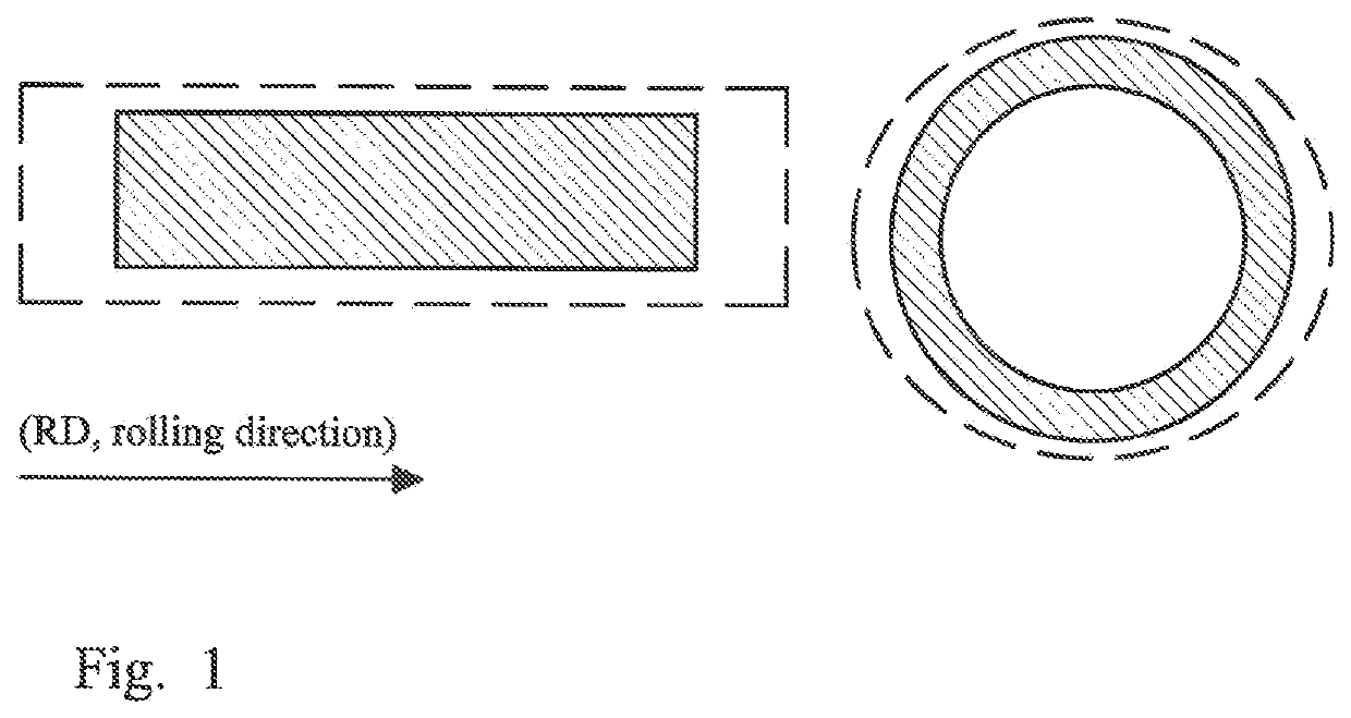
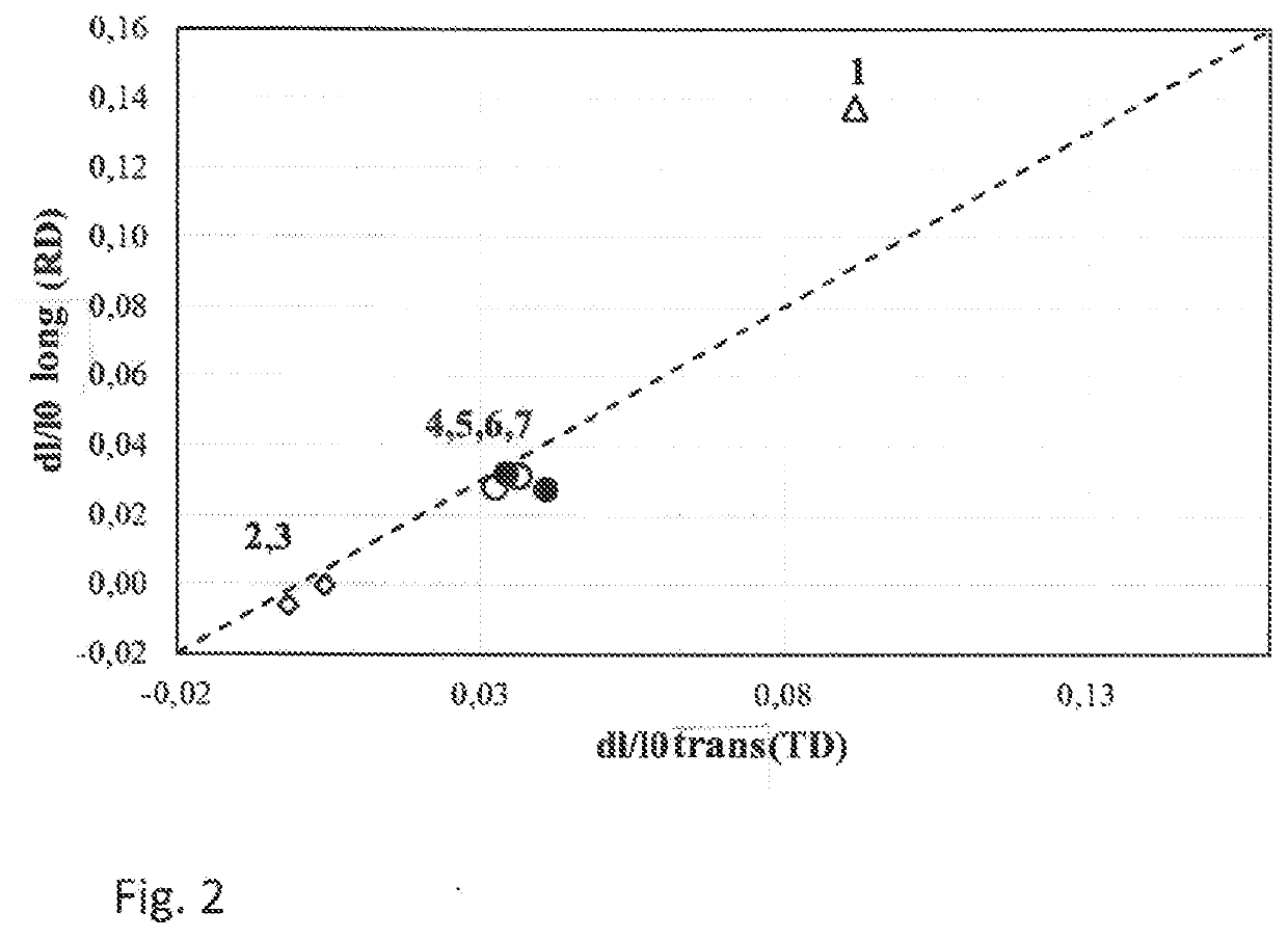
[0063]FIG. 1 shows a diagrammatic illustration of a sheet of a soft magnetic CoFe alloy, showing the permanent growth after annealing. The permanent growth is illustrated diagrammatically in FIG. 1 by the dotted line for a circular and a rectangular sheet.

[0064]The soft magnetic cobalt iron alloy (CoFe) can have a composition of 49 wt % Fe, 49 wt % Co and 2% V and contain additives of Ni, Nb, Zr, Ta or B. In the case of a composition of this type, a saturation polarisation of about 2.3 T is attained, while at the same time the electrical resistance remains sufficiently high at 0.4 μ·Ohm·m.

[0065]The CoFe alloy undergoes heat treatment to achieve the magnetic properties, said heat treatment also being known as magnetic annealing or final annealing. This heat treatment takes place above the recrystallisation temperature and below the phase transition α→α+γ, mostly in the region of 700° C. to 900° C. During the subsequent cooling, ordering takes place, i.e. a B2 superstructure is formed...


PUM

PropertyMeasurementUnit
Temperatureaaaaaaaaaa

Abstract

A method of producing a strip from a CoFe alloy is provided. A slab consisting substantially of 35 wt %≤Co≤55 wt %, 0 wt %≤V≤3 wt %, 0 wt %≤Ni≤2 wt %, 0 wt %≤Nb≤0.50 wt %, 0 wt %≤Zr+Ta≤1.5 wt %, 0 wt %≤Cr≤3 wt %, 0 wt %≤Si≤3 wt %, 0 wt %≤Al≤1 wt %, 0 wt %≤Mn≤1 wt %, 0 wt %≤B≤0.25 wt %, 0 wt %≤C≤0.1 wt %, the remainder being Fe and up to 1 wt % of impurities, is hot rolled and then quenched from a temperature above 700° C. to less than 200° C. The hot rolled strip is cold rolled. The cold rolled strip is stationary annealed to produce an intermediate strip, and the intermediate strip is continuously annealed.

Description

[0001]This U.S. patent application claims the benefit of DE Patent Application No. 10 2019 107 422.3, filed Mar. 22, 2019, the entire contents of which are incorporated herein by reference for all purposes.BACKGROUND1. Technical Field[0002]The invention concerns a strip of a cobalt iron alloy, a laminated core and a method of producing a strip of a cobalt iron alloy.2. Related Art[0003]Magnetically soft cobalt iron alloys (CoFe) with a Co content of 49% are used due to their exceedingly high saturation polarisation which is far above conventional magnetically soft materials. The composition of commercially available CoFe alloys is typically 49 wt % Fe, 49 wt %≤Co and 2% V, some however containing additives of Ni, Nb, Zr, Ta or B. In a composition of this type, a saturation polarisation of about 2.3 T is attained with, at the same time, a sufficiently high electrical resistance of 0.4 μ·Ohm·m.[0004]These types of alloys are used, for example, as highly saturated flux conductors or po...

Claims


Application Information

Patent Timeline
IPC IPC(8): C22F1/10B32B15/01C22F1/00C22C30/00H01F1/147H01F27/25
CPCC22C30/00H01F1/147C22C2202/02C22F1/10H01F27/25B32B15/011C22F1/002C22C19/07C22C38/10C21D8/1261C21D8/1272C21D8/1222C21D8/1233H01F1/16C21D8/12H01F41/02
Inventor VOLBERS, NIKLAS
Owner VACUUMSCHMELZE GMBH & CO KG
Why Eureka
Try Eureka