
Piezoelectric energy harvesting bending structure and the method of manufacturing thereof

a technology of piezoelectric and bending structure, which is applied in piezoelectric/electrostrictive/magnetostrictive devices, piezoelectric/electrostriction/magnetostriction machines, electrical apparatus, etc., can solve the problem of exposed elevation of mechanical constraints in the structure of the cantilever beam, and achieves the reduction of fatigue, reducing the stress at the anchored interface, and enhancing the robustness and durability of the piezoelectric bi

Active Publication Date: 2020-07-09
UNIV GRENOBLE ALPES +1
View PDF0 Cites 2 Cited by
  • Summary
  • Abstract
  • Description
  • Claims
  • Application Information

AI Technical Summary

Benefits of technology

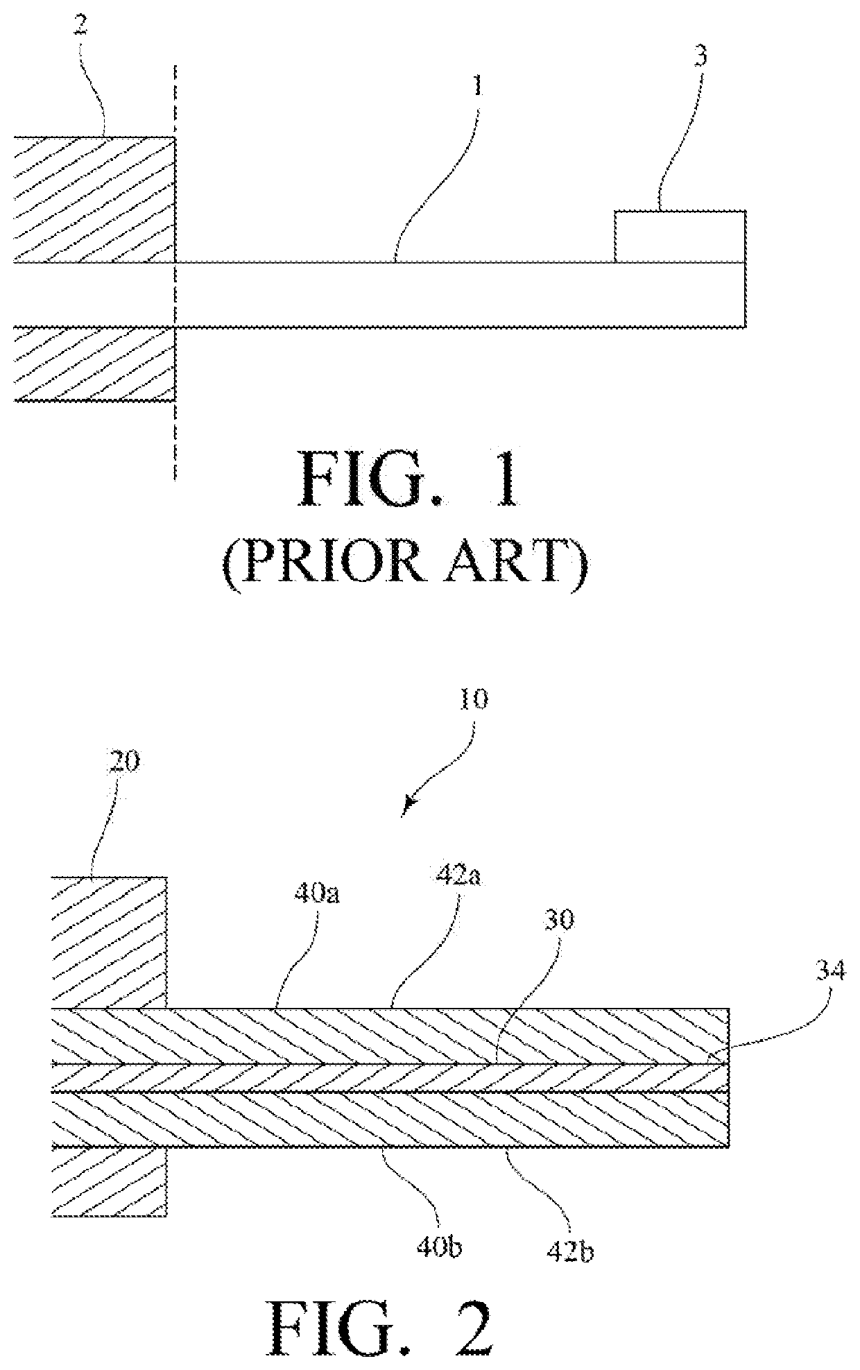
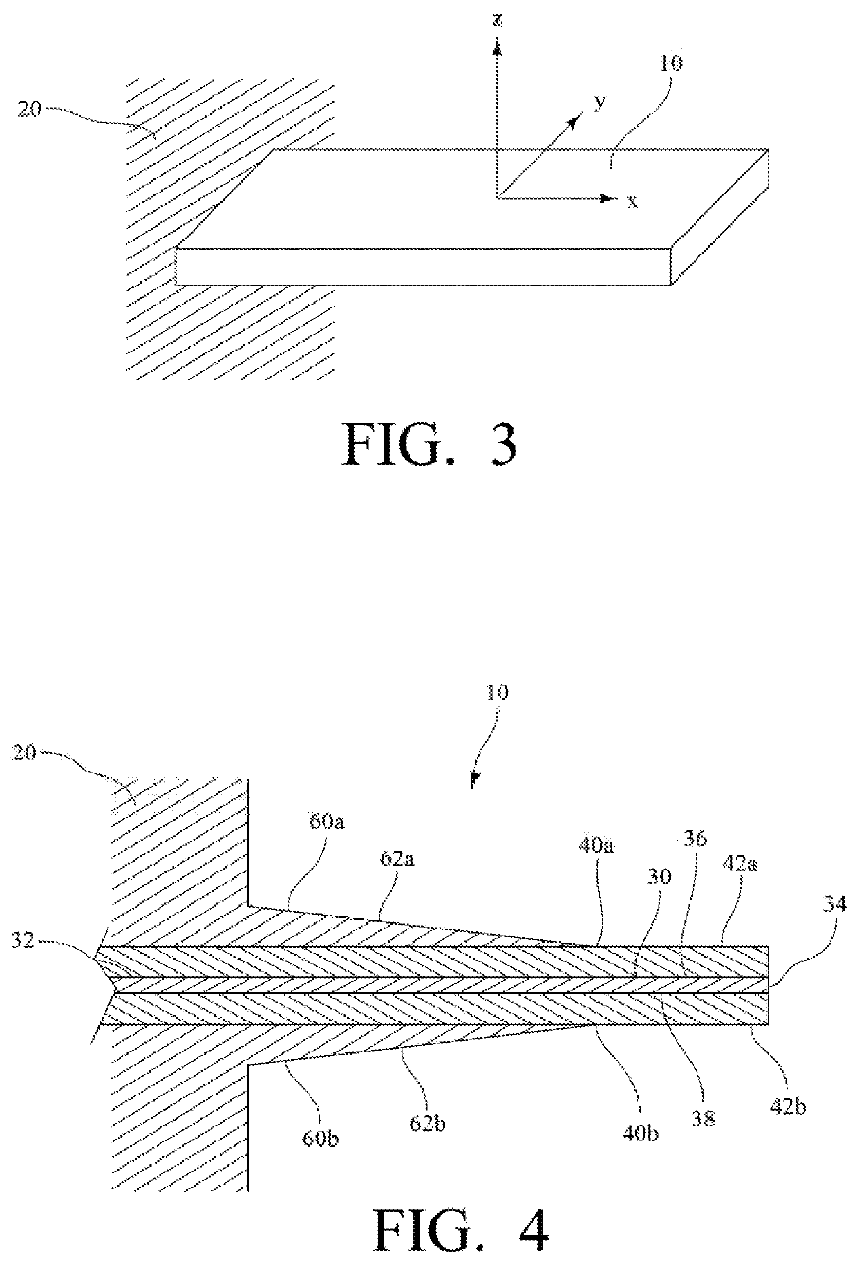
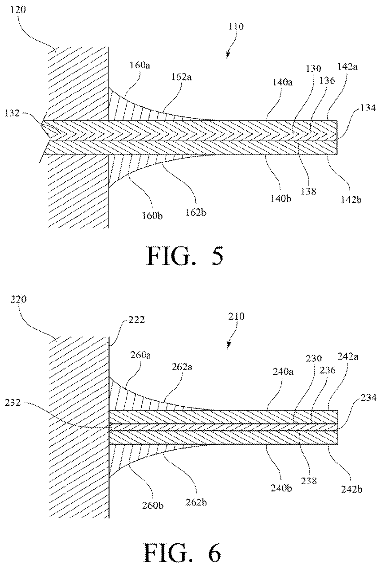
The present invention provides a new design of a piezoelectric bimorph cantilever beam that improves its strength and durability in operation. This is achieved by adding beam stiffeners to the main surfaces of the beam, which help to distribute the mechanical stress from the anchoring interface to the opposite extremity of the beam. This reduces the stress at the anchoring interface and increases the lifetime of the harvester in movement.

Problems solved by technology

Producing electrical energy without battery and life duration constraint for the energy supply source is one of the challenges of electronic devices to comply with current environmental concerns.
This leads to exponential elevation of mechanical constraints in the cantilever beam's structure.
The extremely high stresses observed at this area are sources of damage to the beam with micro-cracks or delamination of the materials impacting dramatically the reliability or the mean time before failure (MTBF) of the device.
The solutions proposed by Benasciutt and Defosseux make the beams modified in shapes and may be crippling for some applications constrained by geometry.
Unfortunately making such a shim is not common process and will require specific tooling and accurate control of the shim thickness variation.

Method used


Image

  • Piezoelectric energy harvesting bending structure and the method of manufacturing thereof
  • Piezoelectric energy harvesting bending structure and the method of manufacturing thereof
  • Piezoelectric energy harvesting bending structure and the method of manufacturing thereof

Examples


Embodiment Construction

[0024]Referring now to the figures and illustrations, the present invention relates to systems and methods of manufacturing piezoelectric Bimorph Cantilever Beam (pBCB) to harvest electrical energy directly from vibrations of the surrounding environment. Although the present invention is not limited the bimorph cantilever beams, this particular embodiment will be used for the description of the present application for the sake of clarity. In this invention, the pBCB is mainly devoted and designed for low frequency vibration in the range of dozens of Hz and is preferably designed to exhibit small dimensions and volume to be integrated into sensor implants for medical applications or sensor nodes for industrial applications. However, the present invention is not limited to these particular design choices.

[0025]The principle of operation is based on mechanical stress created on the piezoelectric layers to produce electrical charges on electrodes that are then collected and rectified by...


PUM


Abstract

A piezoelectric bimorph cantilever beam system includes a shim having a first main surface, a second main surface opposite the first main surface, a proximal end connected to an anchor, and a distal end opposite the proximal end. The system further includes a first piezoelectric layer laminated on the first main surface of the shim and a second piezoelectric layer laminated on the second main surface of the shim. A first beam stiffener is provided over the first main surface of the shim adjacent to the anchor with the first beam stiffener at least partially covering the first piezoelectric layer. A second beam stiffener is provided over the second main surface of the shim adjacent to the anchor with the second beam stiffener at least partially covering the second piezoelectric layer.

Description

RELATED APPLICATIONS[0001]This application claims the benefit of U.S. Provisional Application No. 62 / 528,886, filed Jul. 5, 2017, and U.S. Provisional Application No. 62 / 532,195, filed Jul. 13, 2017 the entire disclosures of which are incorporated herein by this reference.TECHNICAL FIELD[0002]The invention is related to piezoelectric cantilever structures for the production of electrical energy using ambient mechanical vibrations or movements. The piezoelectric cantilever may be used associated with an electronic power management circuit for the optimization of energy harvesting action to powering electric systems such as sensors, electronic circuits or systems.BACKGROUND OF THE INVENTION[0003]Producing electrical energy without battery and life duration constraint for the energy supply source is one of the challenges of electronic devices to comply with current environmental concerns. Thus, energy-harvesting systems are one of the most relevant solutions for battery replacement. Ha...

Claims


Application Information

Patent Timeline
Patent Type & Authority Applications(United States)
IPC IPC(8): H01L41/113H02N2/18H01L41/27H01L41/083H10N30/20H10N30/30H10N30/05H10N30/50H10N30/88
CPCH01L41/0838H01L41/1136H01L41/27H02N2/186H10N30/306H10N30/05H10N30/508
Inventor RUFER, LIBORBASROUR, SKANDARTRIOUX, EMILIEFÉRIN, GUILLAUMEBANTIGNIES, CLAIRELE KHANH, HUNGROSINSKI, BOGDANNGUYEN-DINH, AN
Owner UNIV GRENOBLE ALPES
Learn More