
Covering and Method for Producing Coverings

Active Publication Date: 2020-07-02
BEAULIEU INT GRP NV
View PDF0 Cites 2 Cited by
  • Summary
  • Abstract
  • Description
  • Claims
  • Application Information

AI Technical Summary

Benefits of technology

The patent text describes a method for creating a substrate for a covering that looks like wood or a wood-based material, while using a print pattern applied directly to the substrate. The substrate can be made from a wood-based material or a thermoplastic material with colorants added. The substrate can also contain other components like wood fibers or plasticizers. By adding colorants to the substrate, it can be given a desired appearance and influence the appearance of the print pattern applied on the substrate. This allows for a natural-like appearance without repetitive patterns. The substrate can also be co-extruded with other thermoplastic materials to improve its appearance and cost-effectiveness. The wear layer can be made of a polymeric film or overlay paper. The technical effect of this patent is to provide a method for creating a substrate for a covering that looks like wood or a wood-based material while using a print pattern applied directly to the substrate.

Problems solved by technology

A problem with the coverings described in the prior art is the complexity of the process to produce the coverings as several different types of layers and curing or other treatment steps need to be applied sequentially in order to obtain the coverings.
These various types of sequential steps reduce the flexibility of the different types of decorations that can be obtained and increase the production cost of the coverings.

Method used


Image

  • Covering and Method for Producing Coverings

Examples


example 1

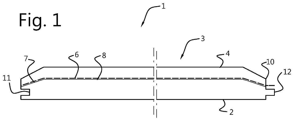
[0090]In a first example, the covering is a covering panel comprising a rigid substrate which comprises a core with a top surface and bottom surface as well as side surfaces. The substrate comprises an extruded PVC material with a colorant distributed uniform throughout the substrate. The substrate has a thickness of about 5 mm. A print pattern is directly applied on the substrate on the top surface. A wear layer is provided on the print pattern on the top surface of the substrate, which wear layer is an acrylated urethane based UV-curable layer. The print pattern and the wear layer together form a surface layer on the top surface of the substrate.

[0091]The covering of example 1 was made by first producing the substrate by extruding PVC whereby a colorant was added during the extrusion process to provide the substrate with a uniform colour, after which a print pattern was directly applied on the top surface using an inkjet printing technique with UV inks. About 8 mL UV ink per m2 su...

example 2

[0092]The covering of example 2 is similar to the covering of example 1 and produced in a similar fashion, but the bottom surface of the substrate is sanded.

[0093]The covering of example 2 was made by first producing the substrate by extruding PVC whereby a colorant was added during the extrusion process to provide the substrate with a uniform colour. After extrusion, the bottom surface of the substrate was sanded, after which a print pattern was directly applied on the top surface using an inkjet printing technique with UV inks.

example 3

[0094]The covering of example 3 is similar to the covering of example 1 and produced in a similar fashion, but it is provided with an embossing pattern. This embossing pattern was provided to the covering by providing the substrate, prior to applying the print pattern to the substrate, with the embossing pattern using a mechanical embossing technique.


PUM


Abstract

The current invention concerns coverings such as a floor covering, wall covering or ceiling covering, said covering comprising at least one substrate and at least one surface layer, said surface layer comprising a print pattern and a wear layer, whereby said print pattern is directly applied to said substrate, and further concerns a method to produce such coverings.

Description

[0001]This application is a continuation of application Ser. No. 15 / 543,374 filed Jul. 13, 2017, which claims the benefit of European Application No. 15151552.5 filed Jan. 16, 2015, and PCT / EP2016 / 050735 filed Jan. 15, 2016, International Publication No. WO 2016 / 113379 A1, which are hereby incorporated by reference in their entirety as if fully set forth herein.TECHNICAL FIELD[0002]The invention pertains to the technical field of coverings such as floor coverings, wall coverings or ceiling coverings and to methods to produce such coverings. Preferably, the invention pertains to the technical field of covering panels.BACKGROUND[0003]Coverings for floor or wall decorations usually comprise a layered structure comprising at least one substrate and at least one surface layer, whereby the surface layer typically comprises a print layer or a print in the form of a pattern, such as for example a wood fibre pattern or brick or stone type pattern. In the case of covering panels, the covering...

Claims


Application Information

Patent Timeline
IPC IPC(8): E04F15/10E04F15/02E04F13/18E04F13/08E04C2/20B32B37/15B32B27/20B32B27/08B44C1/24B44C5/04B32B27/00
CPCB32B2471/00E04F13/0894B32B2307/4026E04C2/20E04F13/18E04F15/105B32B27/00B44C5/0461B32B27/20B44C5/04B32B27/08B44C1/24B32B37/15E04F2201/023B32B2307/554E04F15/02038B44C5/043B41M1/38E04F15/102E04F15/04E04F13/0866E04F13/16B32B38/145B32B2310/0831B32B2310/0843B32B2262/06
Inventor FEYS, JONASLOMBAERT, POLBEVERNAGE, LEO
Owner BEAULIEU INT GRP NV
Learn More