
Particle detection element and particle detector

Inactive Publication Date: 2020-06-25
NGK INSULATORS LTD
View PDF0 Cites 1 Cited by
  • Summary
  • Abstract
  • Description
  • Claims
  • Application Information

AI Technical Summary

Benefits of technology

The present invention aims to increase the collection rate of charged particles by a collecting electrode. A particle detector is used to detect particles based on a physical quantity that changes when the collecting electrode collects charged particles. This results in a higher collection rate of charged particles.

Problems solved by technology

However, according to PTL 1, not all of the charged particles can be collected by the collecting electrode, and some of the charged particles are discharged out of the particle detector.

Method used


Image

  • Particle detection element and particle detector
  • Particle detection element and particle detector
  • Particle detection element and particle detector

Examples


Embodiment Construction

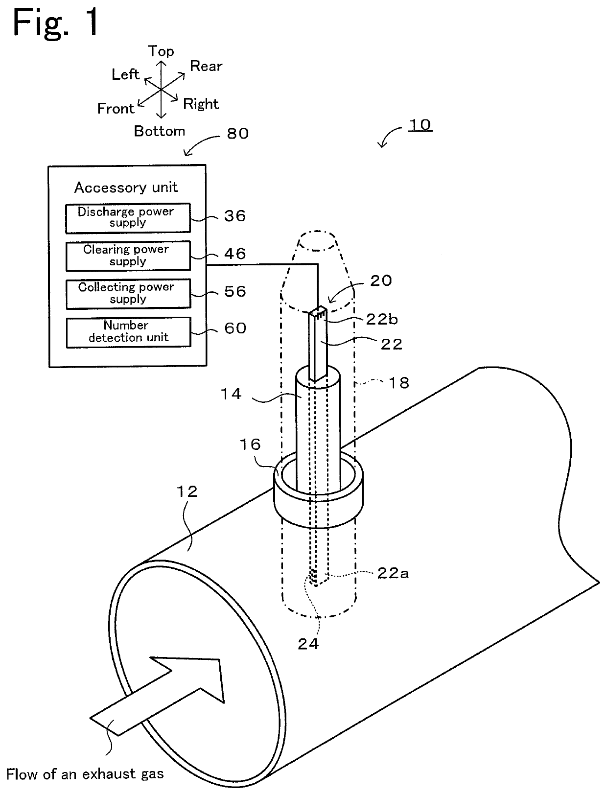
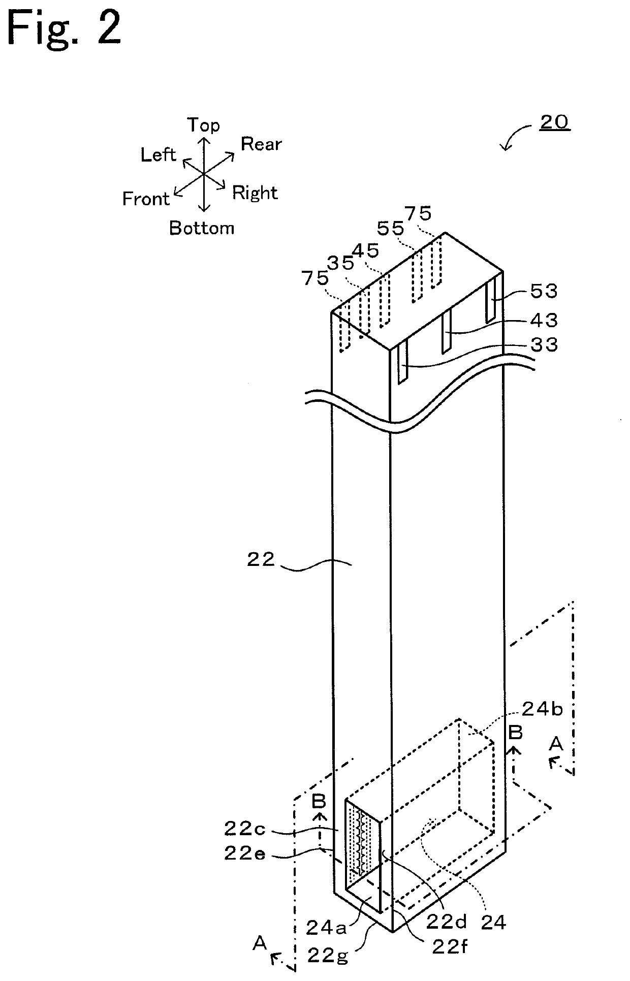
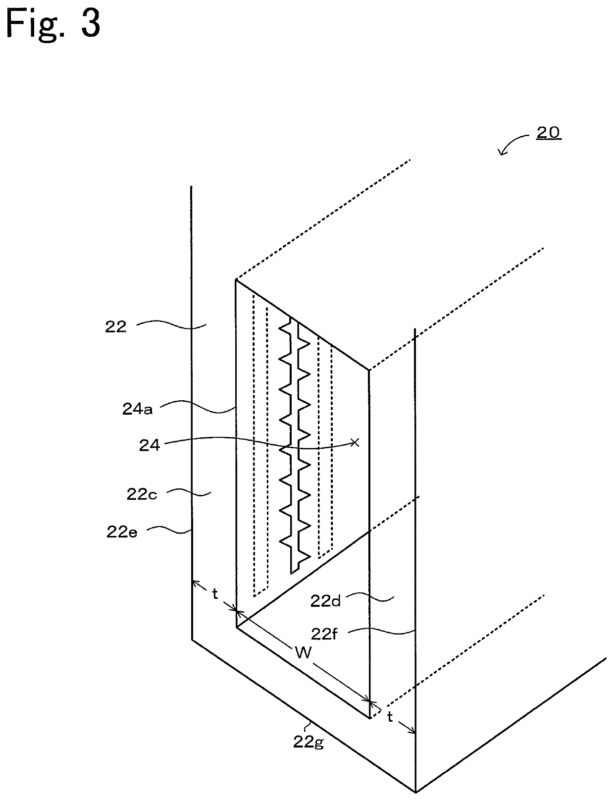
[0025]An embodiment of the present invention will now be described with reference to the drawings. FIG. 1 illustrates a particle detector 10 according to an embodiment of the present invention. FIG. 2 is a perspective view of a particle detection element 20. FIG. 3 is a partial enlarged view of FIG. 2. FIG. 4 is a sectional view of FIG. 2 taken along line A-A. FIG. 5 is a sectional view of FIG. 2 taken along line B-B. FIG. 6 is an exploded perspective view of the particle detection element 20. In the present embodiment, the up-down direction, the left-right direction, and the front-back direction are as illustrated in FIGS. 1 and 2.

[0026]Referring to FIG. 1, the particle detector 10 determines the number of particles 26 (see FIG. 5) contained in exhaust gas that flows through an exhaust pipe 12 of an engine. This particle detector 10 includes the particle detection element 20 and an accessory unit 80 including various power supplies 36, 46, and 56 and a number detection unit 60.

[002...


PUM


Abstract

A particle detection element used to detect particles in gas, the particle detection element includes a housing having a gas flow passage through which the gas passes, wherein the gas flow passage is a rectangular-cuboid-shaped space that extends continuously from a gas inlet having a rectangular shape to a gas outlet having same shape as the shape of the gas inlet, and when the particle detection element is disposed in the flow of the gas so that the gas passes through the gas flow passage, a low-flow-velocity region in which the gas flows at a flow velocity lower than a flow velocity at which the gas passes through the gas flow passage is generated in a region downstream of the gas outlet.

Description

BACKGROUND OF THE INVENTION1. Field of the Invention[0001]The present invention relates to a particle detection element and a particle detector.2. Description of the Related Art[0002]An example of a known particle detector generates ions due to a corona discharge with an electric-charge-generating element, so that particles in measurement target gas are charged due to the ions and changed into charged particles. The charged particles are collected by a collecting electrode, and the number of particles is determined based on the amount of electric charges on the charged particles that are collected (see, for example, PTL 1).CITATION LISTPatent Literature[0003]PTL 1: International Publication No. 2015 / 146456 pamphletSUMMARY OF THE INVENTION[0004]However, according to PTL 1, not all of the charged particles can be collected by the collecting electrode, and some of the charged particles are discharged out of the particle detector. Accordingly, the collection rate at which the collecting...

Claims


Application Information

Patent Timeline
IPC IPC(8): G01N15/06
CPCG01N15/0656G01N2015/0046G01N27/60
Inventor KANNO, KEIICHIOKUMURA, HIDEMASAMIZUNO, KAZUYUKI
Owner NGK INSULATORS LTD
Learn More